background image

3312400 User's Manual

5

Summary of Contents for 3312400

Page 1: ...User s Manual 3312400...

Page 2: ...This document contains proprietary information protected by copyright All rights are reserved No part of this manual may be reproduced by any mechanical electronic or other means in any form without...

Page 3: ...Quick Reference 11 Watchdog Timer 12 Timeout Values 12 Timeout Table 12 Flat Panel VGA 15 SystemResources 16 ETX Connector 18 ETX Connector 19 AWARD BIOS Setup 20 Setup Items 21 Standard CMOS Setup 22...

Page 4: ...What if things go wrong 51 Warranty 52 4 3312400 User s Manual...

Page 5: ...3312400 User s Manual 5...

Page 6: ...nd up to 4 ATAPI devices Ultra DMA transfer 33 66 and 100 MB sec Real time Clock built in chipset with lithium battery backup built on carrier board CMOS data backup of BIOS setup and BIOS default Hig...

Page 7: ...idth is ranging from 25MHz 112MHz VGA SXGA 18 36 bit one two channel LVDS interface TV Out Support NTSC PAL NTSC EIA Japan formats Support 640x480 resolutions Resolution Dual Channel of LVDS 36 bit of...

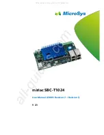
Page 8: ...Board Image 8 3312400 User s Manual...

Page 9: ...ndling computer components 4 Place components on a grounded antistatic pad or on the bag that came with the Single Board Computer whenever components are separated from the system Ordering Codes 33124...

Page 10: ...Board Layout Front LCD1 Eden ESP 5000 LCD2 S3 PN133T DIMM1 Board Layout Back EXT4 EXT3 EXT2 EXT1 10 3312400 User s Manual...

Page 11: ...ference Connectors Lable Function LCD1 LCD TTL Connector 1 LCD2 LCD TTL Connector 2 ETX1 PCI Bus USB Audio ETX2 ISA Bus ETX3 VGA LCD Video COM1 COM2 LPT IrDA M K ETX4 IDE1 IDE2 Ethernet Miscellaneous...

Page 12: ...d by reading port 444H it has to be strobed at preconfigured intervals to keep it from issuing a RESET or NMI The watchdog timer timeout intervals are set by software programming Timeout Values Timout...

Page 13: ...44 68 69 45 69 70 46 70 71 47 71 72 48 72 73 49 73 74 4A 74 75 4B 75 76 4C 76 77 4D 77 78 4E 78 79 4F 79 80 50 80 81 51 81 82 52 82 83 53 83 84 54 84 85 55 85 86 56 86 87 57 87 88 58 88 89 59 89 90 5A...

Page 14: ...meout Value out DX AX pop DX Restore DX AX pop AX ret WT_Refresh push AX Save AX DX push DX mov DX WDT_EN_RF Refresh Timer mov AX INTERVAL Set Timout Value out DX AX pop DX Restore DX AX pop AX ret WT...

Page 15: ...PD11 21 FPD12 22 FPD13 23 FPD14 24 FPD15 25 FPD16 26 FPD17 27 FPD18 28 FPD19 29 FPD20 30 FPD21 31 FPD22 32 FPD23 33 GND 34 GND 35 SHFCLK 36 PANELHS 37 M DE 38 PANELVS 39 ENABLK 40 ENAVEE LCD2 Type Onb...

Page 16: ...tek RTL 8139 A B C 8130 PCI Fast Ethernet NIC 12 PS 2 Mouse 13 Numeric data processor 14 Primary IDE Controller 15 Secondary IDE Controller I O Address Space Adress Description 0000 000F DMA Controlle...

Page 17: ...Graphics Twister 03C0 03DF S3 Graphics Twister 03F6 03F6 VIA Bus Master PCI IDE Controller 03F7 03F7 Floppy Disk Controller 03F8 03FF Communications C0M1 04D0 04D1 Motherboard Resources 0CF8 607F PCI...

Page 18: ...Q6 12 DACK 6 14 DREQ5 16 DACK 5 18 DREQ0 20 DACK 0 22 IRQ14 24 IRQ15 26 IRQ12 28 IRQ11 30 IRQ10 32 IO16 34 GND 36 M16 38 OSC 40 BALE 42 TC 44 DACK 2 46 IRQ3 48 IRQ4 50 VCC 52 IRQ5 54 IRQ6 56 57 PME US...

Page 19: ...PIDE_A2 36 PIDE_A0 38 PIDE_A1 40 N C 42 PIDE_INTRQ 44 PIDE_AK 46 PIDE_RDY 48 VCC 50 51 N C 53 VCC 55 STB 57 N C 59 IRRX 61 IRTX 63 RXD2 65 GND 67 RTS 2 69 DTR 2 71 DCD 2 73 DSR 2 75 CTS 2 77 TXD 2 79...

Page 20: ...This chapter is written to assist you in the proper usage of these features To access AWARD PCI ISA BIOS Setup program press Del key The Main Menu will be displayed at this time Once you enter the Awa...

Page 21: ...tings for power management PnP PCI Configuration This entry appears if your system supports PnP PCI PC Health Status This entry appears CPU temperature for the systemI Frequency Voltage Control Use th...

Page 22: ...to the desired field Press the PgUp or PgDn key to increment the setting or type the desired value into the field IDE Primary Master Slave IDE Secondary Master Slave Options are in sub menu see page 3...

Page 23: ...does not stop for any errors All errors If the BIOS detects any non fatal error POST stops and prompts you to take corrective action All But Keyboard POST does not stop for a keyboard error but stops...

Page 24: ...on this menu IDE Primary Master Selecting manual lets you set the remaining fields on this screen Selects the type of fixed disk User Type will let you select the number of cylin ders heads etc Note...

Page 25: ...5535 Warning Setting a value of 65535 means no hard disk Landing zone Min 0 Max 65535 Warning Setting a value of 65535 means no hard disk Sector Min 0 Max 255 Number of sectors per track We recommend...

Page 26: ...on If this function is enabled and someone attempt to write data into this area BIOS will show a warning message on screen and beep Enabled Activates automatically when the system boots up causing a w...

Page 27: ...elected in these items The choices are Floppy LS ZIP HDD SCSI CDROM Disabled Swap Floppy Drive If the system has two floppy drives you can swap the logical drive name assignments The choice Enabled Di...

Page 28: ...with greater than 64MB of RAM on the system The choice Non OS2 OS2 Video BIOS Shadow Enabled this copies the video BIOS from ROM to RAM effectively enhancing performance and reducing the amount of up...

Page 29: ...imilar to SDRAM CAS Latency Time It controls the time delay in clock cycles CLKs that passes before the SDRAM starts to carry out a read command after receiving it This also determines the number of C...

Page 30: ...chips though the SDRAM density may be up to 256Mbit per chip All SDRAM DIMMs of at least 64MB in size or greater are 4 banked in nature If you are using a single 2 bank SDRAM DIMM set this feature to...

Page 31: ...This is address space not physical memory used The physical memory is allocated and released as needed only when Direct3D makes a create non local surface call AGP 4X Mode Set to Enabled if your AGP...

Page 32: ...f this is enabled then writes to the PCI bus are executed immediately with zero wait states as soon as the PCI bus is ready to receive data But if it is disabled then every write transaction to the PC...

Page 33: ...you enable this feature unless you have many slow PCI devices in your system In that case disabling this feature will prevent the generation of too many retries which may severely tax the PCI bus ISA...

Page 34: ...elect Disabled if you install an add on IDE Control card IDE Prefetch Mode Enable prefetching for IDE drive interfaces that support its faster drive accesses If you are getting disk drive errors chang...

Page 35: ...ed if your system contains a LAN port EEPROM PROTECTION Select Disabled to read and write the onboard EEPROM 128Bytes and Enabled is read only Onboard Serial Port 1 2 Select an address and correspondi...

Page 36: ...tion options 2E8 2F8 3E8 3F8 and Disabled The default setting is Disabled Serial Port 3 Use IRQ Configuration options IRQ3 IRQ4 IRQ10 and IRQ11 The default setting is IRQ11 Onboard Serial Port 4 Confi...

Page 37: ...nterface specification Currently Windows 98 and Windows2000 support ACPI Power Management There are 4 selections for Power Management 3 of which have fixed mode Disabled default No power management Di...

Page 38: ...he modem if any on your system Activity of the selected IRQ always awakens the system Soft Off By PWRBTN The field defines the power off mode when using an ATX power supply The Instant Off mode means...

Page 39: ...m operating environment is Plug and Play aware e g Windows 95 Reset Configuration Data Normally you leave this field Disabled Select Enabled to reset ESCD Extend ed System Configuration Date when you...

Page 40: ...rlay cards or MPEG video cards may not show colors properly Setting Enabled should correct this problem If this field set Enabled any I O access on the ISA bus to the VGA card s palette registers will...

Page 41: ...ptimized Defaults This section describes CPU tempearature for the system Current CPU Temp Show you the current CPU temperature Current CPUFAN Speed Show you the current CPUFAN operating speed Vcore Sh...

Page 42: ...equency and Voltage control for the system Auto Detect DIMM PCI CLK When enabled this item will auto detect if the DIMM and PCI socket have devices and will send clock signal to DIMM and PCI devices W...

Page 43: ...Program basic chipset registers C1h Detect memory Auto detection of DRAM size type and ECC Auto detection of L2 cache socket 7 or below C3h Expand compressed BIOS code to DRAM C5h Call chipset hook t...

Page 44: ...defined See also POST 26h 17h Reserved 18h Detect CPU information including brand SMI type Cyrix or Intel and CPU level 586 or 686 19h Reserved 1Ah Reserved 1Bh Initial interrupts vector table If no...

Page 45: ...lize the APIC for Pentium class CPU 3 Program early chipset according to CMOS setup Example onboard IDE controller 4 Measure CPU speed 2Ah Reserved 2Bh Invoke Video BIOS 2Ch Reserved 2Dh 1 Initialize...

Page 46: ...Reserved 4Bh Reserved 4Ch Reserved 4Dh Reserved 4Eh 1 Program MTRR of M1 CPU 2 Initialize L2 cache for P6 class CPU program CPU with proper cacheable range 3 Initialize the APIC for P6 class CPU 4 On...

Page 47: ...S setup utility 61h Reserved 62h Reserved 63h Reset keyboard if Early_Reset_KB is not defined 64h Reserved 65h Initialize PS 2 Mouse 66h Reserved 67h Prepare memory size information for function call...

Page 48: ...text mode if full screen logo is supported If errors occur report errors wait for keys If no errors occur or F1 key is pressed to continue wClear EPA or customization logo 80h Reserved 81h Reserved E...

Page 49: ...d HDD boot sector information for Trend Anti Virus code 94h 1 Enable L2 cache 2 Program Daylight Saving 3 Program boot up speed 4 Chipset final initialization 5 Power management final initialization 6...

Page 50: ...AD SETUP or BIOS DEFAULTS and then save and exit the setup program Continue to boot with the floppy disk Type AWDFLASH to execute the flash utility When prompted enter the name of the new BIOS image a...

Page 51: ...UTOEXEC BAT file Solution 2 Hot swapping 1 Replace the corrupt chip by a working one The working BIOS doesn t have to be written for your board it just has to give you a chance of booting to DOS BIOSs...

Page 52: ...or disaster Vendor assumes no liability for any damages lost profits lost savings or any other incidental or consequential damage resulting from the use misuse of or inability to use this product Vend...

Page 53: ...ate to contact with us We will do our best to support you for your products projects and business Global American Inc Address 17 Hampshire Drive Hudson NH 03051 TEL Toll Free U S Only 800 833 8999 603...

Reviews: