background image

4

DOK4x HOIAO CxDEN · FD 9912

www.gdts.one

English

Air-to-water heat pump 16 kW with domestic hot water

2 Intended use of the heat pump

2.1 Area of application

The air-to-water heat pump is to be used exclusively for heating
and domestic hot water. It can be used in new or existing heat-
ing systems.
The heat pump is suitable for mono energy and bivalent opera-
tion in outside air temperatures of up to -22 °C.
Proper defrosting of the evaporator is guaranteed by maintain-
ing a heating water return temperature of more than 20 °C dur-
ing continuous operation.
It is not designed for the increased heat consumption required
when a building is being dried out. For this reason, the addi-
tional heat consumption should be met using special devices
provided by the customer. 

2.2 Operating principle

Surrounding air is drawn in by the fan and fed through the evap-
orator (heat exchanger). The evaporator cools the air, i.e. ex-
tracts heat from it. This extracted heat is then transferred to the
working medium (refrigerant) in the evaporator.
The heat is "pumped" to a higher temperature level by increas-
ing its pressure with the aid of the electrically driven compres-
sors. It is then transferred to the heating water via the liquefier
(heat exchanger).
Electrical energy is used to raise the temperature level of the
heat from the environment. Because the energy extracted from
the air is transferred to the heating water, this type of device is
referred to as an air-to-water heat pump.
The air-to-water heat pump consists of the main components
evaporator, fan and expansion valve, as well as the compres-
sors, the liquefier and the electrical control system.
At low ambient temperatures, humidity accumulates on the
evaporator in the form of frost, reducing the transfer of heat.
Uneven accumulation during this process does not indicate a
fault. The evaporator is defrosted automatically by the heat
pump as required. Under certain atmospheric conditions,
steam may be emitted from the air outlet.

Summary of Contents for 16CHOIAOC6

Page 1: ...er no DOK4x HOIAO CxDEN EN FD 9912 System M Comfort Plus 16 kW Installation and Operating Instruction Air to Water Heat Pump in Integral Design Glen Dimplex Thermal Solutions Dimplex 16CHOIAOC6 16IHOIAOC6 ...

Page 2: ......

Page 3: ... line and electric wire 13 6 2 Condensate drain 13 6 3 Connection on heating side 13 6 4 Domestic hot water connection 14 6 5 Temperature sensor connection 15 6 6 Electrical connection 16 6 7 Refrigerant pipe connections 19 7 Commissioning 21 7 1 General 21 7 2 Preparation 21 7 3 Procedure 21 8 Cleaning maintenance 22 8 1 Maintenance 22 8 2 Cleaning the indoor unit 22 8 3 Cleaning the domestic hot...

Page 4: ...t pump 16 kW with domestic hot water 13 Diagrams 32 13 1 Characteristic curves heation 16 kW 32 14 Product information as per Regulation EU No 813 2013 Annex II Table 2 33 15 Warranty certificate 35 16 Information on the use of data 36 17 Declaration of conformity 37 ...

Page 5: ...adhered to This unit can be used by children aged 8 and over and by per sons with limited physical sensory or mental aptitude or lack of experience and or knowledge providing they are supervised or have been instructed in the safe use of the unit and understand the associated potential dangers Children must not play with the device Cleaning and user maintenance must not be carried out by children ...

Page 6: ...orator cools the air i e ex tracts heat from it This extracted heat is then transferred to the working medium refrigerant in the evaporator The heat is pumped to a higher temperature level by increas ing its pressure with the aid of the electrically driven compres sors It is then transferred to the heating water via the liquefier heat exchanger Electrical energy is used to raise the temperature le...

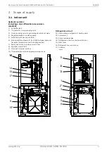
Page 7: ...5 Switch box with heating controller 6 Electric additional heater 2 4 or 6 kW for higher domestic hot water temperatures and for heating support 7 Safety valve start to leak pressure 2 5 bar 8 Expansion vessel 24 l 9 Universal hardware interface 10 Regulated heat circulating pump primary circuit Refrigeration circuit 11 Heat exchanger refrigerant heating water 12 Compressor 13 4 way reversing valv...

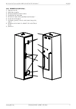
Page 8: ...mp 16 kW with domestic hot water 3 2 Domestic hot water cylinder 3 2 1 MDHW 232 220 litres 1 Magnesium anode 2 Maintenance opening 3 Drainage domestic hot water cylinder 4 Purging pipe heat exchanger 5 Domestic hot water sensor pipe 6 Connection kit included 4 1 5 6 2 3 ...

Page 9: ...um anode 2 Maintenance opening 3 Drainage domestic hot water cylinder 4 Purging pipe heat exchanger 5 Domestic hot water sensor pipe high output capacity 6 Connection kit included 7 Alternative domestic hot water sensor pipe energy opti mised 8 Additional electric heater for domestic hot water flange heater 9 Switch box 8 5 1 2 6 4 3 9 7 ...

Page 10: ...x HOIAO CxDEN FD 9912 www gdts one English Air to water heat pump 16 kW with domestic hot water 3 3 Outdoor unit 1 Evaporator 2 Fan 3 Expansion valve 4 Switch box 5 Connection for refrigerant line 1 2 4 3 5 5 ...

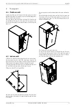
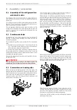
Page 11: ...n be passed directly underneath the pallet To lift from the pallet the indoor unit can be tilted back by up to 45 and lifted by the handles on the back at the top Tilting more than 45 is not permitted Once the two side sections have been removed the device also has the option of inserting support tubes through the holes in the frame The casing panels must be dismantled in the order outlined be low...

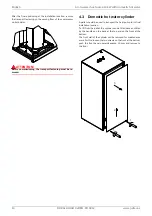
Page 12: ...port fastening must be re moved 4 3 Domestic hot water cylinder A pallet should be used to transport the heat pump to its final installation location To lift from the pallet the cylinder can be tilted back and lifted by the handles on the back at the top and on the front at the bottom The front wall of the cylinder can be removed for maintenance work For this loosen the two screws on the front at ...

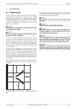
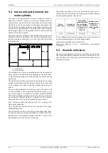
Page 13: ... at the installation location Cap 12 1 on page 27 The responsibility for the heat pump in stallation lies with the specialist system construction company During the installation local requirements such as building reg ulations static load of the building and wind exposure must be accounted for It must be possible to carry out maintenance work without hin drance This is ensured if the clearance dis...

Page 14: ... must be inserted in the designated immersion sleeve on the rear of the cylinder On domestic hot water cylinders MDHW 335 with an additional electric heater two immersion sleeves are located at different heights on the back of the cylinder These are used to mount the domestic hot water sensor Pos 5 bottom position see Figure Cap 3 2 2 on page 7 for high output capacities Pos 7 top position see Fig...

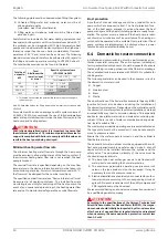
Page 15: ... of the countries in question must be observed 6 3 Connection on heating side Before connecting the heating system to the heat pump the heating system must be flushed to remove any impurities resi due from sealants etc Any accumulation of deposits in the liq uefier may cause the heat pump to completely break down A purging option must be arranged directly upstream and downstream of the indoor unit...

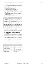
Page 16: ...erated with a suitable frost protection if heat pump systems are implemented in buildings where a power failure can not be detected holiday home 6 4 Domestic hot water connection Installation and commissioning must be performed by an au thorised specialist company The entire system including all factory assembled components should be inspected to ensure that everything is working properly and that...

Page 17: ...n such a way that all weather conditions are taken into consideration and the meas ured value is not falsified Mount on the external wall on the north or north west side where possible Do not install in a sheltered position e g in a wall niche or under a balcony Not in the vicinity of windows doors exhaust air vents ex ternal lighting or heat pumps Not to be exposed to direct sunlight at any time ...

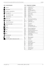
Page 18: ...CxDEN FD 9912 www gdts one English Air to water heat pump 16 kW with domestic hot water 6 6 Electrical connection 6 6 1 Circuit diagram Symbol legend see cap 6 6 2 on page 17 Equipment marking see cap 6 6 3 on page 17 ...

Page 19: ...estic hot water A441 Bivalent A442 Renewable A451 Cooling active B3 domestic hot water thermostat B4 Swimming pool water thermostat E10 1 Electrical heater E10 2 3 Oil gas boiler H5 Remote fault indicator K21 Flange heater K22 Utility block K23 Disable contactor K28 Switching heating cooling K31 Circulation system requirements M13 Heat pump heating circuit 1 M15 Heat pump heating circuit 2 M16 Aux...

Page 20: ...uld be tapped upstream from the utility blocking con tactor or be connected to the household current because otherwise important protection functions could be lost during a utility block Utility block The utility blocking contactor K22 with main contact and auxiliary contact NO contact 13 14 should be designed according to the heat pump output and must be supplied on site The floating NO contact o...

Page 21: ...see device information 6 7 2 Pipe connection The connection points for the refrigerant lines must be estab lished using the brazing process All generally applicable instal lation and work steps must be followed for this During the brazing process the pipe system must be flushed with an inert gas e g nitrogen The adjacent components must be suitably cooled to prevent them being damaged 6 7 3 Leak t...

Page 22: ...m is reached An absolute pressure of at least 0 2 mbar must be achieved during evacuation Pressures below 0 2 mbar are advisable however Close the vacuum pump and start filling immediately Step 4 Filling Once the leakage tightness test and evacuation have been car ried out correctly open the maintenance valves on the indoor unit For refrigerant lines 7 0 m top up the refrigerant accord ingly The h...

Page 23: ...ure that the condensate drain functions properly The outflow from the heating water pressure relief valve must also function correctly The system must be completely filled with refrigerant and the shut off devices completely open 7 3 Procedure The heat pump is commissioned using the master unit or a smart device paired with the pump See the Operation manual for instructions on operation adjustment...

Page 24: ...he system must be cleaned by a heating technician Based on current information we recommend using a 5 phosphoric acid solution for cleaning purposes However if cleaning needs to be performed more frequently a 5 formic acid solution should be used In both cases the cleaning fluid should be at room tempera ture We recommend flushing the heat exchanger in the direc tion opposite to the normal flow di...

Page 25: ...ected from the power supply HINWEIS º º º º º º NOTE Personal protective equipment protective goggles safety shoes and gloves where necessary must be used when work ing on the device Components with plastic parts must be pro tected from impact e g from tools to prevent damage to these components 10 Decommissioning disposal Before removing the heat pump disconnect the machine from the power source ...

Page 26: ... with A7 W55 outdoors Normal operation reduced operation3 dB A 55 54 55 54 3 4 Sound pressure level at a distance of 10 m outdoors4 Normal operation reduced operation 3 dB A 25 24 25 24 3 5 Sound power level in accordance with EN 12102 at A7 W55 indoors dB A 45 45 3 6 Sound pressure level at a distance of 1 m indoors4 dB A 34 34 3 7 Air flow Normal operation reduced operation3 m h 3800 3000 3800 3...

Page 27: ...capacity the bivalence point and regulation should also be taken into consideration These figures are only achieved with clean heat exchangers Information on maintenance commissioning and operation can be found in the respective sections of the installation and operating instructions The specified values e g A2 W35 have the following meaning outside air temperature 2 C and heating water flow tempe...

Page 28: ...ng overpressure bar 10 10 9 5 Dimensions without connections H x W x L mm 1400 x 600 x 600 2100 x 600 x 600 9 6 Connections Cold water domestic hot water circulation inches R 1 external thread R 1 external thread R 3 4 external thread R 1 external thread R 1 external thread R 3 4 external thread 9 7 Heat exchanger area m 3 21 3 6 9 8 Heat losses according to DIN EN 12897 class kWh 24 h 1 15 B 1 63...

Page 29: ...e 0 4 m 1 m 0 5 m 0 5 m Direction of air flow Minimum clearances 460 39 710 40 790 Hatched area footprint 850 1231 600 206 790 538 695 995 95 55 105 40 538 39 4x Ø17 5 Fixing holes base frame for M12 27 110 40 205 108 Foundation Drain pipe Ø50 mm flush with foundation Condensate hose 160 30 30 1 1 1 2 1 4 1 3 1 5 1 3 1 3 1 1 1 2 1 1 1 2 1 6 1 7 4 0 0 174 120 50 866 608 1 8 1 8 1 9 ...

Page 30: ...s one English Air to water heat pump 16 kW with domestic hot water 12 2 Dimension drawing indoor unit 2 8 2 9 2 1 2 10 2 3 2 2 2 7 2 12 2 11 600 1400 544 722 750 113 125 95 0 117 187 490 560 840 910 980 1050 1120 1190 60 ca 60 ca 95 2 14 ...

Page 31: ...AO CxDEN FD 9912 29 Air to water heat pump 16 kW with domestic hot water English 12 3 Dimension drawing domestic hot water cylinder MDHW 232 1360 600 1400 B 20 1305 410 37 38 600 70 70 240 56 3 3 3 5 3 4 3 6 3 7 3 2 3 1 230 ...

Page 32: ...ww gdts one English Air to water heat pump 16 kW with domestic hot water 12 4 Dimension drawing domestic hot water cylinder MDHW 335 600 2060 600 37 38 1265 410 2100 B 20 980 1400 230 70 70 240 56 4 4 4 7 4 6 4 8 4 9 4 2 4 1 4 3 4 5 ...

Page 33: ...oor unit 2 3 Feed through refrigerant line indoor unit 2 7 Flow heating G 1 1 4 2 8 Return heating G 1 1 4 2 9 Flow domestic hot water cylinder G 1 1 4 2 10 Return domestic hot water cylinder G 1 1 4 2 11 Flow bivalent G 1 1 4 2 12 Return bivalent G 1 1 4 2 14 Included pipe set for side connection of the refrigerant lines 3 Domestic hot water cylinder MDHW 232 3 1 Heating water return G 1 1 4 3 2 ...

Page 34: ...20 25 30 35 40 max min 0 1 2 3 4 5 25 20 15 10 5 0 5 10 15 20 25 30 35 40 max min 10 15 20 25 30 35 40 45 50 55 60 65 25 20 15 10 5 0 5 10 15 20 25 30 35 40 at the specified minimum heating water flow Water outlet 2K min water inlet 2K 0K Heat output in kW Air intake temperature in C Air intake temperature in C Coefficient of performance incl proportion of pump output Air intake temperature in C P...

Page 35: ...dB m h Emissions of nitrogen oxides NOx mg kWh Declared load profile XL Water heating energy efficiency ηwh 89 Daily electricity consumption Qelec 8 86 kWh Daily fuel consumption Qfuel kWh Contact details If Cdh is not determined by measurement nthen the default degradation is Cdh 0 9 not applicable Model 16CHOIAOC6 Air to water heat pump yes Water to water heat pump no Brine to water heat pump no...

Page 36: ...NOx mg kWh Declared load profile XL Water heating energy efficiency ηwh 89 Daily electricity consumption Qelec 8 86 kWh Daily fuel consumption Qfuel kWh Contact details If Cdh is not determined by measurement nthen the default degradation is Cdh 0 9 not applicable Model 16IHOIAOC6 Air to water heat pump yes Water to water heat pump no Brine to water heat pump no Low temperature heat pump no Equipp...

Page 37: ...ier are not covered by the warranty If it was not possible to remedy the defect the manufacturer shall either deliver a replacement free of charge or issue a reimburse ment for the reduced value In cases in which replacement is pro vided we reserve the right to apply a reasonable utilisation charge for the period of usage elapsed to date Additional or further claims in particular regarding compens...

Page 38: ...te of the art en cryption methods III Use of service providers Personal data required for maintenance purposes such as your address contact details and framework data on the contract is made available to after sales service partners so that they can carry out maintenance and repair services The control and operating data is evaluated and analysed by a service provider however this service provider...

Page 39: ...s one DOK4x HOIAO CxDEN FD 9912 37 Air to water heat pump 16 kW with domestic hot water English 17 Declaration of conformity You can find and download the current CE conformity declaration at https gdts one m ...

Page 40: ...39 dimplex gdts one www gdts one Geschäftsstelle Österreich Glen Dimplex Austria GmbH Hauptstraße 71 A 5302 Henndorf am Wallersee T 43 6214 20330 F 43 6214 203304 info dimplex at www dimplex at Office France Dimplex SAS 7 rue d Uberach 67590 Schweighouse Sur Moder T 33 3 88 07 18 00 F 33 3 88 07 18 01 dimplex ST dimplex de www dimplex de fr ...

Reviews: