12
DOK4x HOIAO CxDEN · FD 9912
www.gdts.one
English
Air-to-water heat pump 16 kW with domestic hot water
5.2 Indoor unit and domestic hot
water cylinder
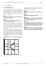
The indoor unit and domestic hot water cylinder must be in-
stalled in a frost-free, dry room on an even, smooth and hori-
zontal surface. The entire base of the indoor unit frame should
lie directly on the floor to ensure an adequate soundproof seal.
The domestic hot water cylinder can be aligned exactly to the
indoor unit via adjustable feet. The surface must have sufficient
load bearing capacity for the weight of the heat pump and the
domestic hot water quantity.
Both parts must be installed so that maintenance work can be
carried out without hindrance. This can be ensured by main-
taining a clearance of approx. 1 m in front of and to the right of
the heat pump.
* 0 m at MDHW 232
0.6 m at MDHW 335
For installation in a corner as outlined above, the domestic hot
water cylinder installation can only take place once the hydrau-
lic, electrical and refrigeration lines have been connected to the
indoor unit.
The flexible lines for flow and return to the domestic hot water
cylinder must be affixed to the indoor unit first, then connected
to the cylinder from above once the cylinder has been posi-
tioned.
The pre-installed domestic hot water sensor on the indoor unit
must be inserted in the designated immersion sleeve on the
rear of the cylinder. On domestic hot water cylinders (MDHW
335) with an additional electric heater, two immersion sleeves
are located at different heights on the back of the cylinder.
These are used to mount the domestic hot water sensor.
Pos. 5 bottom position (see Figure Cap. 3.2.2 on page 7) for
high output capacities.
Pos. 7 top position (see Figure Cap. 3.2.2 on page 7) for energy-
optimised operation.
The cold and hot water connection can then take place. Easy-
to-open connections are recommended for maintenance here.
Neither frost nor temperatures higher than 35°C must occur in
the installation room at any time of the year.
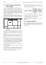
The minimum volume of the room where the heat pump is in-
stalled must be no less than the following value depending on
the refrigerant quantity in the device:
If the refrigerant quantity is increased, the room volume must
be calculated according to the following formula:
[minimum permissible room volume m³] =
[refrigerant quantity in kg] / [permissible concentration
0.39 kg/m³]
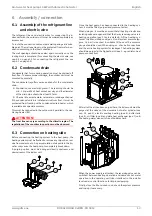
5.3 Acoustic emissions
The heat pump operates silently due to efficient sound insula-
tion. Internal insulation measures should be carried out to pre-
vent vibrations from being transmitted to the foundation or to
the heating system.
1,0 m
1,0 m
0 / 0,6 m*
Perfor-
mance level
Amount of
refrigerant
Permissible
concentration in
the installation
room according
to DIN EN 378
(Tab. C.3)
Minimum per-
missible room
volume for
indoor installa-
tion
16 kW
4.78 kg R410A
0.39 kg/m³
12.3 m³
Summary of Contents for 16CHOIAOC6
Page 2: ......


