


www.gdts.one
DOK41 HOIAO WxDEN · FD 9912
17
Air-to-water heat pump 4 - 6 kW
English
6.7 Refrigerant pipe connections
!!
ATTENTION!
Work on the system must only be performed by authorised
and qualified after-sales service technicians.
Certain requirements with regard to pipe length and rise must
be complied with when installing refrigerant pipes. Once all
conditions are met, the connection of the connecting pipe from
the outdoor unit to the indoor unit can begin.
6.7.1 Requirements for the pipe length
and rise
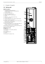
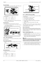
Abb. 6.1:
The indoor unit of the heat pump is already filled with refriger-
ant. The standard pipe length is 3 m. Up to a length of 7 m, no
additional refrigerant filling is required. For pipe lengths over
7 m, the system must be filled with additional refrigerant in ac-
cordance with the table.
!!
ATTENTION!
Incorrect filling with refrigerant could lead to faults during op-
eration.
!!
ATTENTION!
The length of the refrigerant line is calculated based on the
total line length from the respective connection point of the
indoor unit to the outdoor unit.
Incorrect refrigerant filling or refrigerant lines over 10 m result
in a risk of faults during operation and a complete failure of
the heat pump.
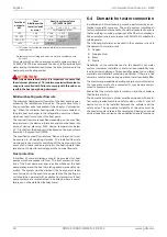
*Example: When installing the 6 kW model at a distance of
10 m, 225 g refrigerant must be added according to the follow-
ing calculation: (10 - 7) x 75 g = 225 g
HINWEIS
ºº
º
ºº
º
NOTE
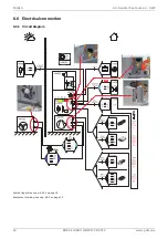
If the indoor unit is mounted 2.5 m or more metres higher or
lower than the outdoor unit, a cooling technology specialist
must perform a separate check to ensure that the devices for
conveying the oil up and down the pipes have been installed
correctly in the exhaust gas pipe. The maximum rise (B) be-
tween the indoor and outdoor units is 5 m.
HINWEIS
ºº
º
ºº
º
NOTE
The specified operating data of the device refers to the stand-
ard pipe length, see device information.
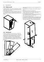
6.7.2 Preparation for pipework
The preparation of the pipework takes place in five steps. One
main cause of refrigerant leaks is incorrect flanging. Flanging
must be carried out carefully and according to the following
steps.
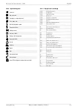
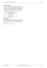
Step 1: Cut pipes
Use the installation kit for pipes
Measure the distance between the indoor and outdoor
unit.
Cut the pipes slightly longer than the measured distance.
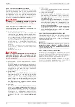
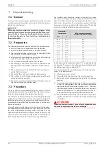
Step 2: Removing burrs
Remove all burrs from the interface of the pipework.
Hold the pipe end downwards so that no burrs can fall into
the pipe.
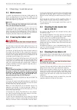
Step 3: Inserting screw nuts
Remove the screw nuts on the indoor and outdoor unit.
Insert the screw nuts into the deburred pipe.
No nuts can be inserted into the pipe after flanging.
Model
Pipe size (mm)
(external diame-
ter and wall
thickness)
Length A (m)
*additional
refrigerant
(g/m)
Gas
Liquid
Normal
Min.
Max.
4 kW
12x1
10x1
7
3
10
75
6 kW
12x1
10x1
7
3
10
75
Outdoor unit
Indoor unit
A
B
Outdoor unit
Indoor unit
A
B
max. 5 m
max. 5 m
Copper pipe
90
q
Tilted Uneven Raw
Pipe
Reamer
Hold facing
downwards
Screw nut
Copper pipe