Glen Dimplex 041HOIAOW2 Installation And Operating Instruction Download Page 14

12

DOK41 HOIAO WxDEN · FD 9912

www.gdts.one

English

Air-to-water heat pump 4 - 6 kW

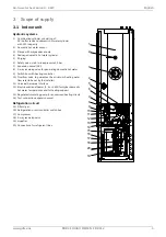
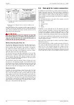
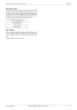
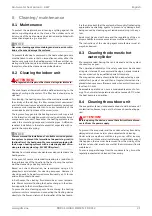
Guideline values for filling and make-up water in accordance with

VDI 2035

For systems with an above-average specific system volume of
50 l/kW, VDI 2035 recommends the use of fully demineralised
water and a pH stabiliser to minimise the risk of corrosion in the
heat pump and heating system.

!!

ATTENTION!

With fully demineralised water, it is important to ensure that
the minimum pH value of 7.5 (minimum permissible value for
copper) is complied with. Failure to comply with this value can
result in the heat pump being destroyed.

Minimum heating water flow rate

The minimum heating water flow rate of the heat pump is guar-
anteed by the installed overflow valve. The procedure for set-
ting an overflow valve is described in the chapter „Commission-
ing“. When the minimum heating water flow rate is undershot,
the plate heat exchanger in the refrigeration circuit can freeze,
which can lead to total loss of the heat pump.
The nominal flow rate is specified depending on the max. flow
temperature in the device information and must be taken into
account during planning. With design temperatures below
30 °C in the flow, the design must be based on the max. volume
flow with 5 K spread for A7/W35.
The specified nominal flow rate (see “Device information”) must
be assured in all operating statuses. The installed flow rate
monitoring is used only for switching off the heat pump in the
event of an unusual and abrupt drop in the heating water flow
rate and not to monitor and safeguard the nominal flow rate.

Frost protection

A method of manual drainage should be provided for heat
pumps which are exposed to frost. The frost protection func-
tion of the heat pump manager is active whenever the heat
pump manager and the heat circulating pump are ready for op-
eration. The system must be drained if the heat pump is taken
out of service or in the event of a power failure. The heating cir-
cuit should be operated with a suitable frost protection if heat
pump systems are implemented in buildings where a power
failure can not be detected (holiday home).

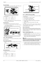
6.4 Domestic hot water connection

Installation and commissioning must be performed by an au-
thorised specialist company. The entire system, including all
factory-assembled components, should be inspected to ensure
that everything is working properly and that there is no leakage.
The enamelled tank in accordance with DIN 4753 is suitable for
drinking water.
The following materials can be used in the consumer circuit in
the domestic hot water circuit:

 Copper

 Stainless steel

 Brass

 Plastic

Depending on the materials used in the domestic hot water
system (customer installation), material incompatibility may
lead to corrosion damage. This especially applies to zinc-plated
materials and materials containing aluminium. If there is a risk
of water contamination during operation, install a suitable filter.
The maximum permissible operating overpressure indicated on
the type plate must not be exceeded. It may be necessary to
mount a pressure reducer.
Ensure that the water supply is turned on and the cylinder is
filled before start-up. 
The domestic hot water cylinder must be equipped with a certi-
fied, spring-loaded membrane safety valve on-site. A shut-off
device must not be installed between the cylinder and the
safety valve. The operational reliability of the valve must be
checked at regular intervals. We recommend having an annual
service inspection carried out by a qualified specialist company.

Total heat 

output in 

kW

Total

Alkaline earths 

in mol/m³ and/

or mmol

Specific system volume

(VDI 2035) in l/kW

< 20



20  < 50



50

Total hardness in °dH

< 50



2.0



16.8



11.2

< 0.11

1

50 - 200



2.0

 11.2



8.4

200 - 600



1.5



8.4

< 0.11

1

 > 600

< 0.02

< 0.11

1

1. This value lies outside the permissible value for heat exchangers

in heat pumps.

Summary of Contents for 041HOIAOW2

Page 1: ...der no DOK41 HOIAO WxDEN EN FD 9912 System M Compact 4 6 kW Installation and Operating Instruction Air to water heat pump in integral design Glen Dimplex Thermal Solutions Dimplex 041HOIAOW2 061HOIAOW...

Page 2: ......

Page 3: ...11 6 2 Condensate drain 11 6 3 Connection on heating side 11 6 4 Domestic hot water connection 12 6 5 Temperature sensor connection 13 6 6 Electrical connection 14 6 7 Refrigerant pipe connections 17...

Page 4: ...2 DOK41 HOIAO WxDEN FD 9912 www gdts one English Air to water heat pump 4 6 kW 16 Information on the use of data 33 17 Declaration of conformity 34...

Page 5: ...to This unit can be used by children aged 8 and over and by per sons with limited physical sensory or mental aptitude or lack of experience and or knowledge providing they are supervised or have been...

Page 6: ...s the air i e ex tracts heat from it This extracted heat is then transferred to the working medium refrigerant in the evaporator The heat is pumped to a higher temperature level by increas ing its pre...

Page 7: ...alve for generating domestic hot water 9 Switch box with heating controller 10 Overflow valve to guarantee the minimum heating water flow rate to be set by the installer 11 Universal hardware interfac...

Page 8: ...6 DOK41 HOIAO WxDEN FD 9912 www gdts one English Air to water heat pump 4 6 kW 3 2 Outdoor unit 1 Evaporator 2 Fan 3 Expansion valve 4 Switch box 5 Connection for refrigerant line 1 2 3 4 5...

Page 9: ...be tilted back by up to 45 and lifted by the handles on the back at the top Tilting over 45 is not permitted without removing the refrigeration circuit beforehand To remove the refrigeration circuit...

Page 10: ...connection 2 Disconnect the plug connections on the refrigeration cir cuit switch box 3 Loosen the mounting screws 4 Pull the refrigeration circuit out at the side and transport it to the intended loc...

Page 11: ...5 The responsibility for the heat pump in stallation lies with the specialist system construction company During the installation local requirements such as building reg ulations static load of the bu...

Page 12: ...ion location at any time of the year The minimum volume of the room where the heat pump is in stalled must be no less than the following value depending on the refrigerant quantity in the device If th...

Page 13: ...n and shut off option must be im plemented upstream and downstream of the indoor unit Once the heat pump has been connected to the heating sys tem it must be filled purged and pressure tested When doi...

Page 14: ...re ready for op eration The system must be drained if the heat pump is taken out of service or in the event of a power failure The heating cir cuit should be operated with a suitable frost protection...

Page 15: ...hat all weather conditions are taken into consideration and the meas ured value is not falsified Mount on the external wall on the north or north west side where possible Do not install in a sheltered...

Page 16: ...K41 HOIAO WxDEN FD 9912 www gdts one English Air to water heat pump 4 6 kW 6 6 Electrical connection 6 6 1 Circuit diagram Symbol legend see cap 6 6 2 on page 15 Equipment marking see cap 6 6 3 on pag...

Page 17: ...Hydraulics WPM A210 Master unit A220 Expansion module WPM A300 Electrical distribution system A350 Router A400 Hydraulic installation general A420 Domestic hot water B3 domestic hot water thermostat E...

Page 18: ...30 V 50 Hz must have a continuous voltage A300 For this reason it should be tapped upstream from the utility blocking contactor or be connected to the household cur rent because otherwise important pr...

Page 19: ...75 g 225 g HINWEIS NOTE If the indoor unit is mounted 2 5 m or more metres higher or lower than the outdoor unit a cooling technology specialist must perform a separate check to ensure that the devic...

Page 20: ...the system Step 1 Preparation Ensure that every pipe liquid and intake side between the in door and outdoor unit is connected correctly Ensure that both maintenance valves on the liquid and intake of...

Page 21: ...ess varies with differ ent lengths of the pipework and the pump output The follow ing table shows the time required for pumping empty Step 4 Filling Once the leakage tightness test and evacuation have...

Page 22: ...wing procedure to set the over flow valve correctly Close all heating circuits that may also be closed during opera tion depending on how the heat pump is being used so that the most unfavourable oper...

Page 23: ...by a heating technician Based on current information we recommend using a 5 phosphoric acid solution for cleaning purposes However if cleaning needs to be performed more frequently a 5 formic acid so...

Page 24: ...from the power supply HINWEIS NOTE Personal protective equipment protective goggles safety shoes and gloves where necessary must be used when work ing on the device Components with plastic parts must...

Page 25: ...m indoors dB A 33 33 3 7 Air flow Normal operation reduced operation3 m h 3000 2600 3000 2600 4 Dimensions weight and filling quantity 4 1 Device dimensions5 indoors without connections H x W x L mm...

Page 26: ...ysis of the economic and energy efficiency of the system other parameters in particular the defrosting capacity the bivalence point and regulation should also be taken into consideration These figures...

Page 27: ...r intake 0 3 m 1 0 m 0 5 m 0 5 m Minimum clearances Direction of air flow 358 40 460 40 17 5 4x Fixing holes base frame for M12 438 540 Hatched area footprint 600 871 500 165 40 40 53 36 676 472 99 16...

Page 28: ...www gdts one English Air to water heat pump 4 6 kW 12 2 Dimension drawing indoor unit 2 1 2 6 2 8 2 7 2 3 2 4 2 5 2 2 544 600 600 2100 0 40 142 212 282 352 422 573 652 880 63 572 37 ca 0 68 118 195 2...

Page 29: ...ough refrigerant line 1 6 Optional feedthrough electric wires 1 7 External dimensions wood design variant 1 8 Included pipe set for optional rear connection of the re frigerant lines 2 Indoor unit 2 1...

Page 30: ...h 0 2 4 6 8 25 20 15 10 5 0 5 10 15 20 25 30 35 40 Air intake temperature in C Coefficient of performance incl proportion of pump output 35 45 55 0 1 2 3 25 20 15 10 5 0 5 10 15 20 25 30 35 40 Air in...

Page 31: ...47 0 6 m h 0 2 4 6 8 25 20 15 10 5 0 5 10 15 20 25 30 35 40 Air intake temperature in C Coefficient of performance incl proportion of pump output 35 45 55 0 1 2 3 25 20 15 10 5 0 5 10 15 20 25 30 35 4...

Page 32: ...ons of nitrogen oxides NOx mg kWh Declared load profile L Water heating energy efficiency wh 97 Daily electricity consumption Qelec 5 12 kWh Daily fuel consumption Qfuel kWh Contact details If Cdh is...

Page 33: ...clared load profile L Water heating energy efficiency wh 89 Daily electricity consumption Qelec 5 51 kWh Daily fuel consumption Qfuel kWh Contact details If Cdh is not determined by measurement nthen...

Page 34: ...covered by the warranty If it was not possible to remedy the defect the manufacturer shall either deliver a replacement free of charge or issue a reimburse ment for the reduced value In cases in which...

Page 35: ...t en cryption methods III Use of service providers Personal data required for maintenance purposes such as your address contact details and framework data on the contract is made available to after sa...

Page 36: ...34 DOK41 HOIAO WxDEN FD 9912 www gdts one English Air to water heat pump 4 6 kW 17 Declaration of conformity You can find and download the current CE conformity declaration at https gdts one m...

Page 37: ...www gdts one DOK41 HOIAO WxDEN FD 9912 35 Air to water heat pump 4 6 kW English...

Page 38: ...36 DOK41 HOIAO WxDEN FD 9912 www gdts one English Air to water heat pump 4 6 kW...

Page 39: ...www gdts one DOK41 HOIAO WxDEN FD 9912 37 Air to water heat pump 4 6 kW English...

Page 40: ...9 dimplex gdts one www gdts one Gesch ftsstelle sterreich Glen Dimplex Austria GmbH Hauptstra e 71 A 5302 Henndorf am Wallersee T 43 6214 20330 F 43 6214 203304 info dimplex at www dimplex at Office F...

Reviews: