background image

Page 14

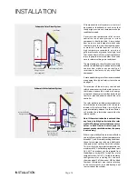
15 mm

discharge

pipe

Expansion

relief valve

Typical Discharge Pipe Arrangement

Dotted line showing

alternative route with

single tundish being used

600 mm max.

P & T 

Relief 

Valve

300 mm

min.

22 mm metal pipe with continuous

fall up to 9m equivalent length (D2).

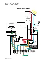
NOTES:


The discharge will consist of scalding

waterand steam. Asphalt, roofing felt

and non-metallic rainwater goods may

be damaged by such discharges.
It is not acceptable to discharge straight

into a soil pipe.

Discharge below

fixed grating

Fixed Grating

Trapped gully

Pressure & Temperature/expansion Relief 

Valve Pipework

The relief valve should be installed to discharge  

in accordance with G3 of the Approved 

Document of the Building Regulations and 

should be piped to where it is visible, but will 

not cause danger to persons or damage to 

materials.

The following information is taken from 

Approved Document G3 of the Building 

Regulations and is provided to assist with 

the design and installation of the discharge 

pipework. However, the information is not 

exhaustive and reference should always be 

made to Approved Document G3 of the Building 

Regulations. The final decision regarding any 

arrangements rests with Building Control and 

it is recommended that their advice is sought 

if you have any concerns regarding this aspect 

of the installation.

The two safety valves will only discharge 

water under fault conditions.  When operating 

normally water will not be discharged.  

The tundish should be vertical, located in the 

same space as the unvented hot water storage 

system and be fitted as close as possible and 

within 600mm of the safety device e.g. the 

temperature relief valve.

The discharge pipe (D2) from the tundish should 

terminate in a safe place where there is no risk 

to persons in the vicinity of the discharge, be 

of metal and:

a) Be at least one pipe size larger than the 

nominal outlet size of the safety device unless 

its total equivalent hydraulic resistance 

exceeds that of a straight pipe 9m long 

i.e. discharge pipes between 9m and 18m 

equivalent resistance length should be at 

least two sizes larger than the nominal outlet 

size of the safety device, between 18 and 

27m at least 3 sizes larger, and so on.  Bends 

must be taken into account in calculating 

the flow resistance.  Refer to the table and 

the worked example.

  An alternative approach for sizing discharge 

pipes would be to follow BS EN 806-2:2005 

Specification for design installation, testing 

and maintenance of services supplying water 

for domestic use within buildings and their 

curtilages.

b) Have a vertical section of pipe at least 

300mm long, below the tundish before any 

elbows or bends in the pipe work.

c)  Be installed with a continuous fall.

Worked Example

The example below is for G1/2 temperature relief valve with a discharge pipe (D2) 

having 4 elbows and length of 7m from the tundish to the point of discharge.

From the table below:

Maximum resistance allowed for a straight length of 22mm copper discharge 

pipe (D2) from a G1/2 temperature relief valve is: 9m subtract the resistance for 

4 x 22mm elbows at 0.8m each = 3.2m.

Therefore the maximum permitted length equates to: 5.8m.

5.8m is less than the actual length of 7m therefore calculate the next largest size.

Maximum resistance allowed for a straight length of 28mm pipe (D2) from a G1/2 

temperature relief valve equates to: 14m.

As the actual length is 7m, a 28mm (D2) copper pipe will be satisfactory.

Sizing of copper discharge pipe ‘D2’ for a temperature relief valve

with a G1/2 outlet size (as supplied)

Size of discharge 

pipework

Maximum length of 

straight pipe

(no bends or elbows)

Deduct the figure 

below from the 

maximum length for 

each bend or elbow in 

the discharge pipe

22mm

Up to 9m

0.8m

28mm

Up to 18m

1m

35mm

Up to 27m

1.4m

INSTALLATION

INSTALLATION

Summary of Contents for StainlessLite D120

Page 1: ... litres Stainless Lite Indirect 90 400 litres Stainless Lite Solar Direct 180 400 litres Stainless Lite Solar Indirect 180 400 litres Stainless Lite Slimline Direct 60 210 litres Stainless Lite Slimline Indirect 60 210 litres StainlessLite Unvented mains pressure water storage in Duplex stainless steel ...

Page 2: ...hey do not play with the appliance This information is provided to assist generally in the selection of equipment Responsibility for selection and specification of our equipment must however remain that of our customer and any experts or consultants concerned with the installation s Please note that we do not therefore accept any responsibility for matters of designselectionorspecification forthee...

Page 3: ...cut out thermostat setting 85 C Max working pressure Primary heat exchanger Indirect models 6 bar Max working pressure Solar heat exchanger Solar models 10 bar Immersion heater rating 3kW 240V AC All cylinders are manufactured in accordance with the requirements of BS EN 12897 The tundish must be positioned so that it is visible to the occupant and is away from electrical devices Components suppli...

Page 4: ...city Figure 3 4 StainlessLiteIndirectSolar Forproviding hotwaterbysolargainsandgasoroilboilers Figure 4 Unvented cylinders must not be used with solid fuel boilers or steam as the energy source Stainless Lite Direct Stainless Lite direct is an electrically heated unvented hot water storage cylinder designed primarily for use with off peak electrical supplies It is supplied fitted with two 3kW imme...

Page 5: ...less Lite indirect is an unvented hot water storage cylinder and is provided with a high efficiency internal primary coil which is designed for use with a gas or oil boiler and is suitable for both open vented and sealed pumped primary systems When used with a sealed heating system the boiler must incorporate its own energy cut out overheat thermostat A high efficiency second solar coil is positio...

Page 6: ...00 37 337 3 35 D400 ASL0031 XL D 118 36 7213 L M 62 15 Y 400 48 448 3 2 x 24 Direct Slimline D60 SL ASL475D60 M D 40 35 2341 62 15 Y 60 13 73 3 12 D90 SL ASL475D90 M D 52 34 2407 62 15 Y 90 16 106 3 12 D120 SL ASL475D120 L D 59 36 4561 M 62 15 Y 120 22 142 3 12 D150 SL ASL475D150 L D 68 36 4609 M 62 15 Y 150 30 180 3 18 D180 SL ASL475D180 L D 76 37 4522 M 62 15 Y 180 31 211 3 18 D210 SL ASL475D210...

Page 7: ...198 n a 3 12 705 475 462 n a n a 348 197 n a n a n a n a n a n a n a n a n a 60 n a 3 12 978 475 734 n a n a 348 197 n a n a n a n a n a n a n a n a n a 90 n a 3 12 1250 475 1006 n a 650 348 197 55 n a n a n a n a n a n a n a n a 119 n a 3 18 1520 475 1278 n a 785 423 197 70 n a n a n a n a n a n a n a n a 150 n a 3 18 1790 475 1548 n a 921 423 197 85 n a n a n a n a n a n a n a n a 179 n a 3 24 1...

Page 8: ...3 35 1992 550 1720 1577 1077 522 IND400 ASL0066 D 118 400 55 455 3 2 x 24 2030 630 1784 1577 1151 542 Indirect Slimline IND60 SL ASL475IND60 B 40 60 14 74 3 12 705 475 462 n a 352 348 IND90 SL ASL475IND90 C 52 90 19 109 3 12 978 475 734 n a 392 348 IND120 SL ASL475IND120 C 59 120 23 143 3 12 1250 475 1006 n a 432 348 IND150 SL ASL475IND150 C 68 150 28 178 3 18 1520 475 1278 n a 462 423 IND180 SL A...

Page 9: ...3 533 n a n a n a n a n a n a 30 5 1 27 0 310 n a n a 41 n a 352 348 n a 28 242 242 179 329 n a n a n a n a n a n a 15 0 59 0 165 n a n a 13 n a 392 348 n a 54 359 359 179 329 n a n a n a n a n a n a 16 5 0 59 0 165 n a n a 17 n a 432 348 n a 75 423 423 179 329 n a n a n a n a n a n a 18 0 59 0 165 n a n a 21 n a 462 423 n a 102 514 514 179 409 n a n a n a n a n a n a 18 5 0 68 0 191 n a n a 25 n ...

Page 10: ...sure relief valve 92 95 6 bar 3 Hot water secondary return 22mm not fitted to smaller sizes see table 2 4 Immersion heater 1 BSP 3kW 5 22mm cold supply compression 6 Immersion heater 1 BSP 3kW 7 Dual control overheat stat pocket 22mm 8 Boiler control sensor pocket spare 9 Primary return 22mm 28mm tails for 400 litre models 10 Primary flow 22mm 28mm tails for 400 litre models Part G3 loose componen...

Page 11: ...draw off 22mm compression 2 Lift up temperature pressure relief valve 92 95 6 bar 3 Hot water secondary return 22mm not fitted to smaller sizes see table 2 4 Immersion heater 1 BSP 3kW 5 22mm cold supply 6 Dual control Overheat stat pocket solar 7 Primary return 22mm 28mm tails for 400 litre models 8 Primary flow 22mm 28mm tails for 400 litre models 9 Dual control Overheat stat pocket boiler 10 So...

Page 12: ...del Selection Guide Max hot water demand Bedrooms Indirect litres Direct litres 1 shower room Bedsit 180 1 bathroom 1 3 180 1 bathroom 1 3 210 1 bathroom 1 shower room 1 3 210 1 bathroom 1 shower room 1 3 250 1 bathroom 2 shower rooms 2 4 250 1 bathroom 2 shower rooms 2 4 300 2 bathrooms 1 shower room 3 4 300 2 bathrooms 1 shower room 4 5 400 2 bathrooms 2 shower rooms 4 5 400 INSTALLATION INSTALL...
Page 13: ...cting pipe work is kept to a minimum Shower Fittings Aerated taps are recommended to prevent splashing Any type of shower mixing valve canbeusedaslongasboththehotandcoldsuppliesaremainsfed However allmains pressure systems are subject to dynamic changes particularly when other hot and cold taps showersareopenedandclosed whichwillcausechangesinthewatertemperature at mixed water outlets such as show...

Page 14: ...the discharge be of metal and a Be at least one pipe size larger than the nominaloutletsizeofthesafetydeviceunless its total equivalent hydraulic resistance exceeds that of a straight pipe 9m long i e discharge pipes between 9m and 18m equivalent resistance length should be at leasttwosizeslargerthanthenominaloutlet size of the safety device between 18 and 27m at least 3 sizes larger and so on Ben...

Page 15: ...lve Pump ERV Combination Inlet Group Combines elements 1 2 and 3 below 1 Pressure Reducing Valve This must be fixed near the cylinder The cold water supply to any mixer taps showers must be taken from thecoldwatertappingofthisvalvetoensure balanced hot and cold pressures This valve isfactorysettoensurethecorrectoperating pressure for the Stainless Lite 2 Non Return Valve This is integral with the ...

Page 16: ...thermostat Shouldthisoperate investigatethe cause for the operation cut out before pressing theredresetbuttonlabelledsafety Ifthereisno apparent fault adjust the control setting down slightly to prevent nuisance tripping If another heat source is used to heat the cylinder and this is allowed to raise the water temperature excessively then the overheat thermostat will trip This is likely on solar t...

Page 17: ...ipe provided a Listed double check valve or some other no less effective backflow prevention device is permanently connected at the inlet to the circuit and the temporary connection is removed after use Alternatively a CA device can be used which will allow the system to be permanently connected to the cold mains supply The primary system can then be topped up when required in the same way as an o...

Page 18: ... valve will only allow heat transfer as required under control of the solar controller The solar pocket provided accommodates an 8mm diameter sensor which with the sensor located in the solar collector or in the flow pipe immediately adjacent to the collector will provide the information required by the solar controller Note If the motorised valve is not used then any factory built hydraulic stati...

Page 19: ...w the blending valve can be piped onsite Figure 1 shows the cold water port of the blending valve connected to the mains cold water supply before the inlet control group This arrangement is completely unacceptable and illegal because the water is allowed to expand in to mains cold water supply the vessel will be charged to the incoming mains supply which may be considerably higher than the working...

Page 20: ...nvented Cylinder T Anti Gravity Check Valve Pressure Relief Valve Anti Gravity Check Valve Standard 10 way wiring junction box Not supplied This valve must be fitted on the return to the solar panels and be suitable for higher temperatures operation Not supplied No isolation valve should be installed between the solar circuit and the safety valve pressure relief valve Solar Controller Schematic Sh...

Page 21: ...ED PUMP OVERRUN OPTION Br Bl G Y B Br Or ELECTRONICS 1 9 8 7 6 5 4 3 2 10 11 12 N L 1 2 3 4 OFF ON OFF ON HW CH 1 2 3 4 Room Thermostat Central Heating Control 1 C 2 2 C 1 Dual Cylinder Stat Overheat Stat Spade connectors required for earth connections Control Stat L N E Mains Supply Fed Via Double Pole Isolator 230 VAC 5 Amps HTG VALVE HW VALVE Typical schematic wiring diagram for an unvented ins...

Page 22: ...sinfection agent can cause damage unless the appliance is adequately flushed and refilledwiththemainswaterimmediatelyoncompletionofthedisinfectionprocedure Damage caused through a failure to do this adequatelywillnotbecoveredbythewarranty Forthereasonsmentioned werecommendthe useofanonchlorinebaseddisinfectantsuchas Fernox LP Sterox as manufactured by Cookson Electronics when carrying out disinfec...

Page 23: ... surge in flow may be experienced which disappears as the pressure in the system stabilises This is quite normal with these types of systems and does not indicate a fault In some areas the water will initially appear cloudy but will quickly clear when left to stand This is nothing to be concerned about and is due to aeration of the water WARNING Ifwaterisseenflowingthroughthetundish thisindicatesa...

Page 24: ...s are free from obstruction and blockage and are not passing any water 5 Check the condition and if necessary descale the heat exchangers in hard water areas 6 Check that water pressure downstream of pressure reducing valve is within the manufacturers limits 7 Check operation of motorised valve 8 Check the pressure on the air side of the expansion vessel This must be done when the volume in the cy...

Page 25: ...are isolated from the mains before re setting the energy cut out If the immersion heater s need replacing this should be done with the units supplied from Gledhill Building Products Limited Same day despatch to approved installers can be arranged by telephoning 01253 474402 Discharge From Relief Valves If cold water is discharging from the expansion relief valve into the tundish check the pressure...

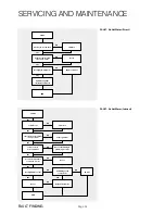
Page 26: ...nd Re set END YES YES YES NO NO NO Switch on Set programmer Re set check wiring plumbing is correct Re set Is all wiring to the controls ok Replace thermostat Re wire START Is boiler on Is hot water programmer in on position Is zone valve in correct position Is control temperature set at 60ºC 65ºC Has high limit cut out Re set END YES YES YES YES YES YES YES NO NO NO NO NO NO NO SERVICING AND MAIN...

Page 27: ...O Clear obstructions Is system free from restrictions blockages YES NO Is pressure reducing valve in combination valve working Clean or replace as required Is expansion vessel charge pressure correct Replace ERV TPRV Replace PRV END START Is pressure downstream of pressure reducing valve correct Is valve seal and seat clean undamaged Is heater operating at less than 60ºC Re set temperature NO YES ...

Page 28: ...ar 1 SG022 5 flexible hose 1 SG024 7 12 litre expansion vessel 1 XG190 8 18 litre expansion vessel 1 XG191 9 24 litre expansion vessel 1 XG192 10 35 litre expansion vessel 1 XG193 11 Wall mounting bracket for 35 litre expansion vessel 1 XG058 12 22mm 2 port valve indirects only 1 XG083 13 Junction wiring box 12 way 1 XG129 14 Control and overheat limit thermostat 1 XG212 15 15mm x 22mm tundish 1 X...

Page 29: ...Stourbridge West Midlands DY8 1PA TELEPHONE 01384 442611 FAX 01384 442612 Water Savings Water Related Costs Can Be Reduced By Good Plumbing Practice TAPS MIXERS SHOWERS Unregulated 25 30 l m Regulated 10 12 l m Over 20 l m 5 6 or 8 l m 2 tap half open Fitted with regulator Unregulated 4 Fixing Options For Taps Mixers 1 MK Range Combined Regulators Aerator forscrewingontoTaps Mixerswithinternal ore...

Page 30: ...hold e Taking the lead for team lifts As more than one person is required for these products ensure that one person is taking the lead This may be you so ensure that each person that is helping is made aware of the weight and of the items listed within this assessment Make sure you and any others helping know the route you intend to take that it is clear of any obstructions Never jerk the load as ...

Page 31: ...has been carried out strictly in accordance with BS6700 For heavy use installation where constant usage reheat is required titanium immersion heaters should be fitted The registration document enclosed with the unit is completed and returned within 60 days of purchase by the owner Evidence of purchase and date of supply must be submitted upon making a claim Guidance in the event of a problem If yo...

Page 32: ...ombination chloride sulphate Max 300 mg l in total 9 2 5 Whereappropriatetheunithasbeenregularlymaintainedasdetailedintheinstallationandserviceinstructions 9 2 6 Defects caused by corrosion or scale deposits are not covered by any Guarantee 9 2 7 Where we agree to rectify any defect we reserve the right to undertake the work on our own premises 9 2 8 We will not accept any labour charges associate...

Page 33: ... i the Purchaser shall hold the goods in a fiduciary capacity for us and shall store the same separately from any other goods in the Purchaser s possession and in a manner which enables them to be identified as our goods ii the Purchaser shall immediately return the goods to us should our authorised representative so request All the necessary incidents associated with a fiduciary relationship shal...

Page 34: ...ate will then be issued to the customer Heating and Hotwater Industry Council HHIC www centralheating co uk demonstrating compliance with the appropriate Building Regulations and then handed to the customer to keep for future reference Failure to install and commission this equipment to the manufacturer s instructions may invalidate the warranty but does not affect statutory rights Customer name T...

Page 35: ...ame Telephone No Comments Signature SERVICE 05 Date Engineer name Company name Telephone No Comments Signature SERVICE 07 Date Engineer name Company name Telephone No Comments Signature SERVICE 09 Date Engineer name Company name Telephone No Comments Signature SERVICE 02 Date Engineer name Company name Telephone No Comments Signature SERVICE 04 Date Engineer name Company name Telephone No Comments...

Page 36: ...ment Gledhill Building Products reserve the right to modify products without prior notice It is advisable to check the product technical detail by using the latest design and installation manuals available from our technical support team or on our website It is an offence to copy or adapt this document without consent of the owner Gledhill Building Products Limited Sycamore Estate Squires Gate Bla...

Reviews: