Page 33
mCHP
BOILERMA
TE
A-CL
ASS
COMMISSIONING 6.0
6.3 COMMISSIONING mCHP UNIT &
BOILERMATE
(a) Check that the mCHP BoilerMate front panel switch is in ‘On’ position and the
mode switch is in the ‘normal’ position.
(b) The mCHP unit will not start i.e there will be no 240V ac start signal at BoilerMate
terminal ‘SL-O’ until:-
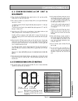
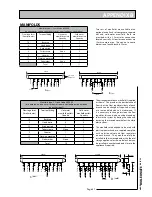
• The heating clock calls for heating indicated by display segment V1.1 being on
(see figure 6.2)
• Store sensors are calling for heat indicated by display segments H1.1 and H1.2
being on (see figure 6.2)
(c) Commission the mCHP unit as per manufacturer’s instructions and ensure that
the flow temperature is set at maximum i.e. greater than 77
o
C.
After the mCHP start sequence, which could take 8 - 12 minutes, the thermal store
will begin to heat up and the store temperature can be read from the display (see
section 3.6)
(d) Check that the mCHP boost mode and the auxiliary electric heater is functioning
correctly. This can be done when the mCHP is running and the central heating is
on by removing the top store sensor, S6 from the pocket i.e. simulating that the
store is not heating at correct rate.
This will be indicated by controller display segment H2.2 being on (See figure 6.2).
When mCHP boost is active, there will be a 230V ac signal at terminal ‘SL-B’ in the
BoilerMate.
After this test,
ensure that the sensor is inserted and secured into the
pocket.
(e) To check manual electric backup heating , move operation switch on front panel
display from ‘normal’ to ‘switch’ position. The electric backup operation can now
be observed.
6.4 COMMISSIONING SPACE HEATING
(a) The central heating is best commissioned when the store is hot and therefore
should be carried out after procedure 6.3.
(b) Set heating clock to continuous and ensure
that the room thermostat is calling for heat.
This will be indicated by display segments
V1.3 and V1.4 being on respectiveley. The
BoilerMate controller will now:-
• Switch on the central heating pump and
this will be indicated by display segment
H2.2 being lit.
(c) With flow to the central heating circuit,
bleed every radiator and pipework high
points until air or air/water mix has been
removed.
(d) Wait until the heating circuit has reached its
normal mean temperature of approximately
75
o
C before balancing the system in the
usual way to achieve a temperature drop
between 10 and 12
o
C.
(e) Ensure that the system has been flushed
and treated.
(f) Set the clock as per manufacturer’s
instructions supplied with the appliance
and ensure that the room thermostat and
appliance instructions are left with the
user.
LED
Description
H1.1
Middle store sensor calling for heat
H1.2
Bottom store sensor calling for heat
H1.3
Spare
V1.1
HW Programmer calling for heat
V1.3
CH Programmer calling for heat
V1.4
Room thermostat calling for heat
H2.1
PHE pump on
H2.2
CH Pump on
H2.3
mCHP/System pump on
V2.1
mCHP on
V2.2
Switch on / electric boost on
V2.4
mCHP boost mode on
Note:
if both ‘dots’ are flashing then the
controller is working. However it is a
warning of limited/alternative control
functionality
@&LASHING
,OCKOUT&AILURE
@&LASHING
#ONTROLLERW
(
6
6
(
(
6
6
(
6
6
(
(
6
6
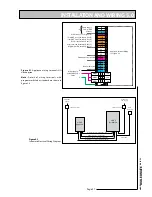
Figure 6.2
Summary of Contents for mCHP BMA 225
Page 44: ......

