background image

Page 35

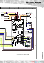
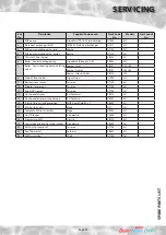
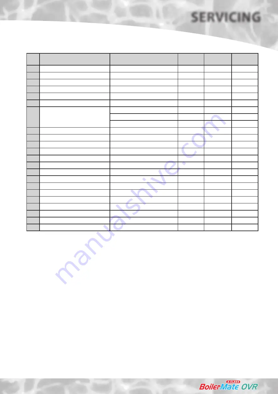
Key 

No.

Description

Supplier/Components

Stock Code 

No

Models

Gas Council 

No.

1

PHE pump

Grundfos UPR 15-50 (modulating)

GT089

All

2

Plate heat exchanger (PHE)

SWEP 24 Plate heat exchanger

GT017

All

3

PHE pump isolating valve - inlet

Vemco

GT133 

All

4

PHE pump isolating valve - outlet

Vemco

GT135

All

5

CW inlet Y-line strainer

XB314

Al

6

Boiler / Central heating pump

Grundfos ErP Ready 15-50

XB523

All

7

Boiler / Central heating pump isolating 

valves

Vemco - Inlet

XB121

150, 180

Vemco - Outlet

XB121

150, 180

Vemco,  Inlet & Outlet

XB122

220

8

Main PCB controller

Argus Vision

GT490

All

9

Bottom store sensor

Tasseron

GT198

All

10

Middle store sensor

Tasseron

GT198

All

11

Top (OHT) sensor

Tasseron

GT199

All

12

Front panel display

R H Technical

XB414

All

13

Front panel display wiring harness

R H Technical

XB057

All

14

Internal fuses/circuit protection

MCB Single Pole 6A x 1

XB449

All

15

DIN Rail terminals

Wago

NSI

All

16

Complete DIN rail assembly

Wago

XB220

All

17

On-Off rocker

Arcoelectric

CA006

All

18

Programmer EMC

Grasslin 

XB215

All

19

Central heating and hot water rocker

Arcoelectric

XB059

All

20

DHW In/Out Sensor x 2

Tasseron

GT198

All

21

Rod Thermostat

Cotherm

XB081

All

22

3kW Immersion

Shell

GT198

All

SP

ARE

 P

ART

S LIST

SERVICING

Summary of Contents for BMAS 150 OVR

Page 1: ...sure hot water supply system incorporating a thermal store Design Installation Servicing Instructions Model Numbers BMAS 150 OVR BMAS 180 OVR BMAS 220 OVR All models comply with the Hot Water Association specification for integrated thermal stores ...

Page 2: ...uilding Regulations was accepted if the Benchmark Logbook was completed and this was then left on site with the customer With the introduction of a self certification scheme the Benchmark Logbook is being replaced by a similar document in the form of a commissioning check list and a service interval record is included with all gas appliance manuals However the relevant Benchmark Logbook is still b...

Page 3: ...g Control TheBoilerMateA ClassOVRisnotintendedforusebypersons includingchildren with reduced physical sensory or mental capabilities or lack of experience or knowledge unlesstheyhavebeengivensupervisionorinstructionconcerninguseoftheappliance by a person responsible for their safety Children should be supervised to ensure that they do not play with the appliance The information in this manual is p...

Page 4: ...f lime scale To comply with this requirement the hardness of the mains water should be checked by the installer and if necessary the optional factory fitted electronic in line scale inhibitor should be specified at the time of order for hardness levels between 200 and 300 ppm mg l Wherethewaterisveryhardie300ppm mg l andabovethe optionalpolyphosphate type inhibitor should be specified at the time ...

Page 5: ...5 35 Max heating system size 17 kW 20 kW 25 kW Typical Dwelling Types Bedrooms 2 3 2 4 3 5 Bathrooms 1 2 1 2 En suite shower 2 1 4 2 TECHNICAL DATA DESIGN Notes 1 Inmanycases largepropertieswillbenefitfromhaving2smallerapplianceslocated adjacent to the areas of peak hot water use This will allow 2 heating zones to be provided and remove the need to provide trace heating on the hot water system 2 A...

Page 6: ...r inlet sensor 9 Store temperature sensors 10 Overheat sensor 11 Y type strainer flow regulator 12 A feed and expansion cistern complete with ballvalve overflow fitting and cold feed open vent pipework assembly is supplied separately Optional Equipment A seven day digital clock programmer to control the space heating in conjunction with a room thermostat A no clock multi zone option Hot and cold w...

Page 7: ...HNICAL DATA DESIGN Note The Appliance dimensions above do not allow for the100mm high installation base The following table of minimum cupboard dimensions only allow the minimum space required for the appliance including the F E cistern and any extra space required for shelving etc in the case of airing cupboards etc must be added Minimum Cupboard Dimensions Model Height D Width E Depth F BMAS 150...

Page 8: ... on an installation base to allow the pipe runs to connect to the appliance from any direction It is easier if all pipes protrude vertically in the cut out area shown Compression or push fit connections can be used All pipe positions are approximate and subject to a tolerance of 20mm in any direction A 15mm cold water supply and a 22mm warning overflow pipe will also be required for the separate f...

Page 9: ...onmenu A0 A9 onthe controller is hidden It is only possible to get to the appliance selection using the reset button Left hand S2 on the main board When going from the show locking error to show blocking error menu see opposite do notreleasethebuttonbutholditfor10seconds Thedisplaywillchangefrom c to A Atthisstage the push button S2 can be released The appliance type can now be selected by using r...

Page 10: ...store in dry pocket S1 S2 are in single housing S2 T Overheat 2 2 10 S3 T DHW in 3 11 In cold water inlet pipe Wet i e direct S4 T DHW out 4 12 In hot water outlet pipe Wet i e direct S5 T Tank bottom 5 13 Bottom of store in dry pocket for store charging S6 T Tank middle 1 9 Middle of store in dry pocket for store charging Sensor Control Set Points Display Sensor Temp S1 Middle store sensor on 68 ...

Page 11: ...heaters and the hot water circuit of combination boilers to reduce the rate of accumulation of lime scale To comply with this requirement the hardness of the mains water should be checked by the installer and if necessary the optional factory fitted in line scale inhibitor should be specified atthetimeoforderforhardnesslevelsbetween 200 and 300 ppm mg l Where the water is very hard ie 300ppm mg l ...

Page 12: ...their recommendations It is also essential that if an alternative pipework material system is chosen the manufacturer confirms that the design criteria of the new system is at least equivalent to the use of BS EN Standard copper pipework and fittings Taps Shower Fittings Aerated taps are recommended to prevent splashing Any type of shower mixing valve can be used as long as both the hot and cold s...

Page 13: ...e A Class i e the maximum static pressure in the store must not exceed 0 6 bar If any radiators are located above the level of the BoilerMate A Class the system should be designed so that gravity circulation does not occur when the heating pump is not running To be certain of preventing this it is recommended that a check valve or valves are fitted on the vertical flow pipes The water level in the...

Page 14: ...r is smaller but in any instance it should not be less than 22mm copper tube Note There should be no valves in the pipework connecting the boiler to the BoilerMate A Class The heating circuit operates on the normal primary boiler temperatures i e 82 C flow and 71 C return Therefore any traditional hot water radiators or convectors can be used with this system and no special over sizing of the heat...

Page 15: ...red on the flow adjacent to the boiler and depending upon the pipe layout a manual air vent may also be required on the return adjacent to the boiler see boiler installation insructions Boiler sited with dipped flow and return pipes to the BoilerMate Any boiler must be fitted with an overheat thermostat i e it must be approved for use in a sealed system An automatic air vent will be required on th...

Page 16: ...le on page 5 The radiators will only get hot when the boiler is firing Itisimportantthattheflowratesthroughthese radiators is adjusted to the minimum required at the lockshield valves on the radiators If this is not done the performance of the BoilerMate will be adversely affected The height of the water level in the F E cistern must provide the minimum head required by the boiler and must be at l...

Page 17: ...ezones bathrooms within the property The electrical supplies from each appliance to the boiler will need twinning so that the boiler will operate on a call from either both appliances Both primary pumps and the primary pipework sizes should be checked to ensure that they are adequate for the system that has been installed If necessary an extra pump should be fitted on the common primary return pip...

Page 18: ... of the appliance during the night will cause noise problems If this is the case switch the rocker to timed and set the first on time on the clock to switch on at least an hour before the first heating and hot water demand is required each morning BoilerMateA CLASS OFF RAPID FLASHING Normal Overheat safety trip PUSH BUTTON To reset appliance Control circuit power supply Grasslin clock Central Heat...

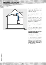
Page 19: ...ing the appliance on a suitable sound deadening material i e carpet underlay or similar Cupboardtemperatureswillnormallybehigherthaninaconventionalsystemandthe design of the cupboard and door will need to take this into account No ventilation is normally required to the cupboard A suitable location will be needed for the separate feed and expansion cistern This will often be at high level in the c...

Page 20: ...f the base and the front panel removed by unscrewing the 2 screws and lifting the door up and out ready for connection of the pipework and electrical supplies The feed and expansion cistern support shall be installed ensuring that the base is fully supported and the working head of the appliance is not exceeded and the recommended access is provided for maintenance see the Technical Data section F...

Page 21: ...estic hot water to taps H Incoming mains cold water I Drain valve is not provided with the appliance An optional primary return for pumped summer towel rail circuit available at time of order Note The safety open vent and cold feed expansion must be connected to the F E cistern using the pipework assembly provided Do not alter or connect any pressure relief device to the vent pipe of this water he...

Page 22: ...GREEN GREY GREEN YELLOW G Gr G Y WIRE COLOUR LEGEND BLACK ORANGE YELLOW WHITE RED B Or Y Y Y Wh R 2 DOUBLE POLE CHANGE OVER SWITCHES WITH CENTRE OFF FACTORY FITTED CLOCK STANDARD OPTION 6B 2A 5B 2A 5B 3A 4B 3A 1A 6B 4B 1A Remove Link To Fit Room Thermostat Br B Or Wh Br Br Br Bl Bl Bl G Y G Y G Y Br SL F SL B SL R SL H SL W E E E L1 L2 L3 N N N MCB 1 6A HTG Switched Live Room stat S W Live L HW Sw...

Page 23: ... J34 J28 J5 J3 J31 J9 L L N N E E M M All wire sizes 0 5mm2 unless otherwise stated Y Flat Ribbon Cable 1 Connection only used if Modulating Pump is fitted 1 1 Boiler ON OFF Heating S L Hot Water S L Frost Protection S L Room Stat S L DHW Pump Boiler Heating Pump Pump Bl Br B G Y L N E M I 1a 1 1b Rocker Switch Terminal Connections O White Covering G Y Or Wh BL J33 J32 J34 J28 J29 J5 J3 J30 J31 J9...

Page 24: ... by the installer to connect this to the appliance Note When fitting the cistern at higher level this must not be fitted more than 6 meters above the base of the BoilerMate A Class appliance Obviously any pipework in the roof space and the feed and expansion cistern will need to be adequately insulated to protect against frost damage Combined feed and open vent pipe arrangements must not be used N...

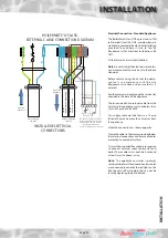
Page 25: ...are suitably labelled Note Donotattempttheelectricalworkunless you are competent to carry it out to the above standards Before commencing check that the power source is in accordance with the Site Requirements section and ensure that it is isolated Runtheexternalwiringthroughtheserviceslot provided in the base of the appliance The twin and earth 2 core input cable from the isolator to the applianc...

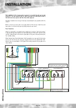
Page 26: ...ermanent live for another purpose The boiler manufacturers wiring instructions should be read in conjunction with this manual Before switching on the electrical supply check all the factory made terminal connections to ensure they have not become loose during transit Frost Protection When frost protection is required for the whole house or where a base temperature is required during cold weather t...

Page 27: ...asting and reliable cable terminations in immersion heaters Electrical Power Control Supplies The existing power control wiring should be re connected to the new appliance as follows L N E Permanent 230V 50Hz Electrical Supply Minimum 1 cable fused at 5A N N E N L_3 L_1 L_2 SL_W SL_H SL_R SL_B SL_F E E RoomThermostat N E L SL MCB 6 A ON OFF L SL_B E N E L_P N_P Boiler Wiring Terminals Local Isolat...

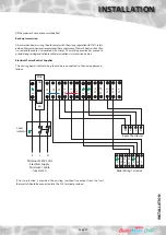
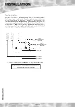
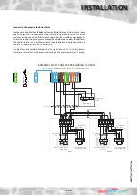
Page 28: ...STALLATION Zoned heating systems BoilerMate is available in a no clock multi zone version for use where a property has to have its space heating zoned Where this appliance version is to be used it is recommended that the BoilerMate is located on a raised platform in the cupboard creating a space below the appliance to locate the zoning equipment The recommended height of the platform from the floo...

Page 29: ...e option MCB 1 6A N E SL W SL B SL R L1 L2 L3 N N N SL F SL H E E Zone 1 Hot Water Time Control Zone 2 4 Core cable 4 Core cable INSTALLATION INSTALLATION Connecting the zones to the BoilerMate ThespaceheatingflowshouldbetakenfromtheBoilerMateconnectionintothespace below the platform The flow can now be split into the appropriate amount of zones and a controlling zone valve fitted to each branch E...

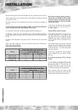
Page 30: ...ed be sure to allow for the increased volume of water in the primary circuit due tothethermalstore seetheTechnicaldata section for volumes In most cases the quantities shown opposite will be adequate for up to a typical 3 4 bedroom property Primary Water System Treatment Although the BoilerMate has no special water treatment requirements the radiators and other parts of the circuit will benefit fr...

Page 31: ...s fully flushed Commissioning the BoilerMate control system For maximum system efficiency the store thermostat must be in control of the boiler i e the boiler cycles on the store thermostat and not on its integral thermostat The BoilerMate control system will automatically commission itself to match the actual performance of the installed boiler However the operation of the control system should b...

Page 32: ...mperature should settle at about 52o C Close this tap and open the hot bath tap at maximum flow rate and record the flow rate and the hot water temperature in the Benchmark logbook c Close the hot water tap s and after few seconds the plate heat exchanger pump will stop running and display segment H2 1 will turn off d It is recommended that the hot water rocker is left on constant so that hot wate...

Page 33: ...se refer to the information provided by the pump manufacturer opposite 11 DO ensure that the bypass valve for the heating system if fitted is set correctly 12 DON T use a combined feed and vent on BoilerMate installations 13 DON T use a BoilerMate on a sealed primary i e closed system 14 DON T use pipe smaller than 28mm between the boiler and the BoilerMate when the boiler rating exceeds 20kW abou...

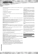
Page 34: ... Free of charge replacements for any faulty components are available from Gledhill during the in warranty period normally 12 months After this spares should be obtained direct from Gledhill Spares or through any of the larger plumbers merchants specialist heating spares suppliers Help and advice is also available from the Technical Helpline on 01253 474584 However all components are readily access...

Page 35: ...let XB122 220 8 Main PCB controller Argus Vision GT490 All 9 Bottom store sensor Tasseron GT198 All 10 Middle store sensor Tasseron GT198 All 11 Top OHT sensor Tasseron GT199 All 12 Front panel display R H Technical XB414 All 13 Front panel display wiring harness R H Technical XB057 All 14 Internal fuses circuit protection MCB Single Pole 6A x 1 XB449 All 15 DIN Rail terminals Wago NSI All 16 Comp...

Page 36: ... C will allow the BoilerMate A Class to provide a satisfactory performance Check that the store is charging to at least 75 C Check that the hot water plate heat exchanger pump stops and starts when the hot water tap is opened and closed Check that the plate heat exchanger pump is set at maximum speed Check that the space heating and hot water load is not greater than the boiler output and that the...

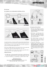
Page 37: ...on 4 for Taps Mixers Information by courtesy of AQUAFLOW REGULATORS LTD Haywood House 40 New Road Stourbridge West Midlands DY8 1PA TELEPHONE 01384 442611 FAX 01384 442612 Water Savings Water Related Costs Can Be Reduced By Good Plumbing Practice 4 Fixing Options For Taps Mixers 1 MK Range Combined Regulators Aerator forscrewingontoTaps Mixerswithinternal orexternalthreadsontheirnoses AntiVandal m...

Page 38: ...Page 38 APPENDIX APPENDIX B ...

Page 39: ...these allow one or two persons to have a purposely designed hold at the top of the appliance to ensure easy lifting at the top of the product e Taking the lead for team lifts As more than one person is required for these products ensure that one person is taking the lead This may be you so ensure that each person that is helping is made aware of the weight and of the items listed within this asses...

Page 40: ...Page 40 APPENDIX D NOTES ...

Page 41: ...Page 41 NOTES ...

Page 42: ...structions 9 2 6 Defects caused by corrosion or scale deposits are not covered by any Guarantee 9 2 7 Where we agree to rectify any defect we reserve the right to undertake the work on our own premises 9 2 8 We will not accept any labour charges associated with replacing the unit or parts for any of the following products listed 9 2 9 If the newly fitted water heater is not in regular use then it ...

Page 43: ...if the Purchaser fails to make payment in full for the goods within the time stipulated in clause 4 hereof ii if the Purchaser not being a company commits any act of bankruptcy makes a proposal to his or her creditors for a compromise or does anything which would entitle a petition for a Bankruptcy Order to be presented iii if the Purchaser being a company does anything or fails to do anything whi...

Page 44: ...able Due to a programme of continuous improvement Gledhill Response reserve the right to modify products without prior notice It is advisable to check the product technical detail by using the latest design and installation manuals available from our technical support team or on our website Issue 04 02 16 ...

Reviews: