


Page 29
1
COM
2
OFF
3
ON
E
L
E
N
AS
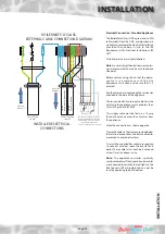
TP5000 Programmable room
Thermostat
Zone valve Spring return
with auxiliary switch
Junction Box
3 core 0.75mm²
flex
L2
L N E AS
E
1
2
3
COM OFF ON
L1
SL
E
N
L
5 Core flex from
zone valve
1
COM
2
OFF
3
ON
E
L
E
N
AS
TP5000 Programmable room
Thermostat
Zone valve Spring return
with auxiliary switch
Junction Box
3 core 0.75mm²
flex
L2
L N E AS
E
1
2
3
COM OFF ON
L1
SL
E
N
L
5 Core flex from
zone valve
1 2 3 4
Single channel
Grasslin clock
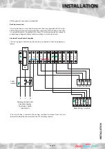
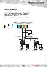
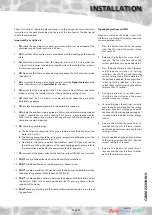
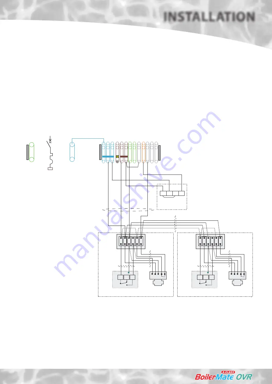
BOILERMATE MULTI-ZONE EXTERNAL WIRING DIAGRAM
Note: Terminals L3 AND SL-H must be linked in a no clock/multi-zone option.
MCB 1
6A
N
E
SL-
W
SL
-B
SL
-R
L1
L2
L3
N
N
N
SL
-F
SL
-H
E
E
Zone 1
Hot Water Time
Control
Zone 2
4 Core cable
4 Core cable
INST
ALL
ATION
INSTALLATION
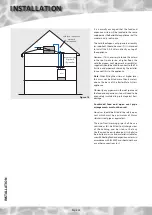
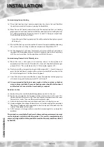
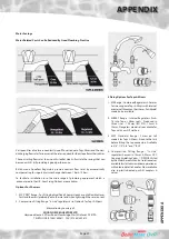
Connecting the zones to the BoilerMate.
The space heating flow should be taken from the BoilerMate connection into the space
below the platform. The flow can now be split into the appropriate amount of zones
and a controlling zone valve fitted to each branch. Each flow can then be piped to its
radiator zone and the heating return brought back to the space below the platform.
The heating returns can now be connected together before a single connection is
made to the heating return on the BoilerMate.
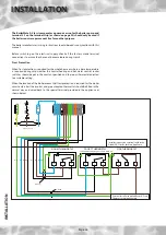
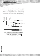
A typical way of providing heating and hot water time control is shown below.
However, other methods can be used such as using a 3 channel programmer if required.
Summary of Contents for BMAS 150 OVR
Page 38: ...Page 38 APPENDIX APPENDIX B ...
Page 40: ...Page 40 APPENDIX D NOTES ...
Page 41: ...Page 41 NOTES ...


