


2013 Glacier Bay 2780 Owners Manual
Chapter 9:
2780 O
PERATION AND
S
CHEMATICS
9.1 O
PERATION OF
S
TANDARD
E
QUIPMENT
9.1.1
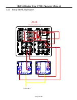
Battery Layout and Management
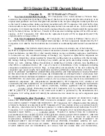
The 2780 is equipped with three batteries, which are located in theaft battery compartment on the transom
wall.. A cranking battery is installed on each side, and a dedicated house battery is installed in the center.
Wire leads run through the hull harness to the battery management panel which islocated under the helm
seat. See section 6.5 & 6.5.1 for information regarding the operation of this panel. The engine cranking
leads run aft, through a hull rigging tube, The negative engine leads are connected to the common battery
ground using a negative buss also located in the aft rigging compartment.
The house battery provides the power for a majority of your DC accessories. The main battery lead runs to
the “HOUSE” switch on the battery management panel. From there current is routed to the dash and circuit
breaker through the 50 amp “DC Main” breaker located in the left side of the battery management panel.
During normal operation this breaker can remain in the “ON” position, and the “HOUSE” switch can be
used to control the flow of current. The main ground for all DC accessories is tied into the common ground
on all batteries. For a detailed drawing of the battery management panel connections, see section 9.3.12. .
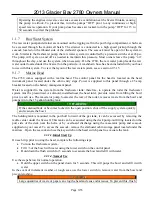
9.1.2
Additional Emergency Parallel
As an additional feature, the 2780 management panel contains a secondary “EMERG PARALLEL” switch.
It allows you to mechanically link the starboard “cranking” battery to the house battery. Furthermore,
engaging both “EMERG PARALLEL” switches will connect all three batteries into a single bank. The
switches should remain in the “OFF” position when not in use. To prevent voltage spikes or drops which
can damage electrical components, you should trip the DC Mains 1 breaker prior to cranking engines with
the house battery in parallel. Once you are running, the breaker can be reset to allow the full alternator
output to power the electronics. This is a safety feature and should not be used in-lieu of the VSR’s to
charge batteries while underway. Doing so, could result in premature battery failure and increases the risk
of electrical failure while at sea.
9.1.3
Bilge Pumps / Float Switches
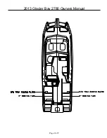
Your 2780 is equipped with two 1500 GPH bilge pumps located aft and two 500 GPH pumps forward. Each
pump is connected to a float switch which automatically triggers the pump when water comes to rest in the
bilge. The float switches are connected to the battery management panel through the hull harness and
receive power from the breakers on the right side of the panel. These breakers are constantly energized and
ensure the safety of your boat even when the battery switches are in the “off” position. The pumps can be
manually engaged using the switch at the dash.
The aft bilge pumps are located behind the aft rigging compartment and can accessed through the
inspection plates in the motorwell, forward of the engines. The forward bilge pumps are located under the
inspection plate in front of the head in the portside cabin and under the starboard side storage liner .. The
wiring for these pumps is secured to the centerline stringer which is visible from the hatch. Inspect the
operation of your bilge pumps and their connections at least annually. To do so, activate the pump by
removing the pump from the base and flipping it upside down. Then check the operation using the manual
switch. Keeping your bilge areas clean can also help extend the life of your pump.
9.1.4
Freshwater System
Page 9-51
Summary of Contents for 2013 Isle Runner 2780
Page 1: ...2013 OWNER S MANUAL...
Page 11: ...2013 Glacier Bay 2780 Owners Manual Page 3 10...
Page 12: ...2013 Glacier Bay 2780 Owners Manual 3 2 STANDARD EQUIPMENT ON ALL GLACIER BAYS Page 3 11...
Page 13: ...2013 Glacier Bay 2780 Owners Manual 3 3 2780 OPTIONS LIST Page 3 12...
Page 22: ...2013 Glacier Bay 2780 Owners Manual 5 6 STEERING SYSTEM DIAGRAM STANDARD Page 5 21...
Page 24: ...2013 Glacier Bay 2780 Owners Manual 5 8 POWER STEERING SYSTEM DIAGRAM Page 5 23...
Page 42: ...2013 Glacier Bay 2780 Owners Manual 7 12LEWMAR MAINTENANCE Page 7 41...
Page 43: ...2013 Glacier Bay 2780 Owners Manual Page 7 42...
Page 44: ...2013 Glacier Bay 2780 Owners Manual Page 7 43...
Page 45: ...2013 Glacier Bay 2780 Owners Manual Page 7 44...
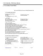
Page 46: ...2013 Glacier Bay 2780 Owners Manual 7 13 Hurricane Preparedness Page 7 45...
Page 47: ...2013 Glacier Bay 2780 Owners Manual Page 7 46...
Page 48: ...2013 Glacier Bay 2780 Owners Manual Page 7 47...
Page 58: ...2013 Glacier Bay 2780 Owners Manual Page 10 57...


