


15
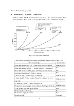
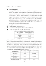
Camera viewable angel
θ
(degree) = 2 tan
-1
(D/2f)
D (mm) = CCD size (horizontal, vertical, or diagonal)
f (mm) = Camera focal length
Example
:
3
1
′′
CCD Camera (Width 4.8mm × Height 3.6 mm), convert its viewable angel
:
f (focal length)
2.8mm
4 mm
6 mm
8 mm
12 mm
θ
(Viewable Angle)
81.2
°
61.9
°
43.6
°
33.4
°
22.6
°
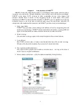
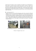
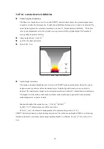
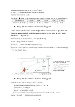
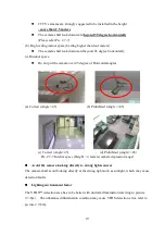
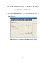
Image detection distance calculation- Starting point
As the camera is installed in a certain height with a certain depression angel, there will
be a fan-shaped area right under the camera could not be covered, which we refer to
blind area. Figure 2-7.3
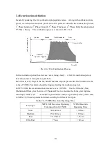
Camera image coverage distance L
1
= H
c
/ [tan(
θ
1
+
θ
2
/ 2)]
H
c
(m)
:
Height of camera installed
θ
1
(degree)
:
Camera installation depression angle
θ
2
(degree)= 2 tan
-1
(D
v
/2f)
:
Camera image vertical viewable angel (D
v
is CCD vertical length,
“f” is focal length value)
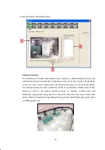
Pic. 2.7-3 Parameters of camera installation
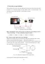
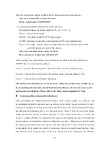
Image detection distance calculation – Ending point
(a) Calculate the farthest detection distance of flame
Farthest detection distance of flame : D
f
(m) = f
× H
p
/ h
f
f
(mm)
:
Lens focal length
h
f
(mm)
:
Object height in CCD
h
f
(mm) equals to VFDS minimum height ratio of flame detection*CCD sensor height (mm)
H
p
(m) = H
f
cos(
θ
1
)
:
The flame reflection height
L
1
:Nearest detection distance from camera
H
c
(m)
:
Height of camera installed
θ
1
(degree)
:
Camera angle of depression
θ
2
(degree)= 2 tan
-1
(D
v
/2f)
:
Camera vertical viewing angle
(D
v
stands for CCD vertical
H: height of target object
D: The farthest detection distant
H
p
: height of object projection
Height of object projection H
p
=H*cos(
θ
1
)
Camera
Blind
area
Fire


