background image

Standard Detail with

Remote Indicator

Standard Detail

Standard Detail with

4 Wire Smoke Detector

Wiring
Details
Modes 
B and C

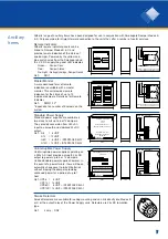
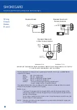
The Smokegard B & C Dampers are supplied pre-wired with a 5-core pvc insulated flex for
connection as follows:

RED

24v+ DC supply input

BLACK

24v- DC  supply input

BLUE

24v DC +output with damper tripped

YELLOW

24v DC +output with damper set

WHITE

- VE input if local led permanently required when 

supply voltage switches to operate dampers

The yellow and blue wires are only utilised if remote indication of damper status is required.
These 2 wires should be insulated if not required.

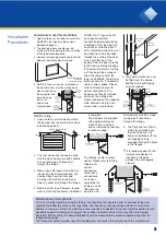
MODE C only

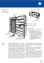
The Mode C Smokegard has an integral LED to indicate the blade position of the
damper (open/closed). It fits into the right of the 2 circular apertures located on the
top frame of the damper.

A key is also provided for local control or test. To test the damper, insert the key into
the left of the 2 circular apertures.

NOTE:

Should access to the pcb be required for any reason ISOLATE the DC supply prior
to undertaking any work.

IMPORTANT: SMOKEGARD UNITS REQUIRE A SMOOTH AND STABILISED 24V DC SUPPLY

+/- 2 VOLTS WITH A MAXIMUM 3 VOLT AC RIPPLE

R

B

B

Y

W

+

-

24v DC

SUPPLY

260mA

R

B

Bu

Y

+

-

24v DC

SUPPLY

W

N/C  N/O    C

260mA

LOAD

L1 in

L2

Apollo S65 
detector shown

R

B

Bu

Y

W

+

-

24v DC

supply voltage

Max IDC = 300MA

O
R
G

Remote Indicator

Externa

For Perm

8

SMOKEGARD

Door, Wall and Partition Mounting Smoke and Fire Dampers

Summary of Contents for SMOKEGARD

Page 1: ...struction Smoke or fire operated Stainless steel interlocking blades and side seals for maximum smoke retardation Galvanised steel frame Easy key reset 1 hour door 2 hour wall mounting fire ratings SMOKEGARD Door Wall and Partition Mounting Smoke and Fire Dampers ...

Page 2: ...ith Stainless Steel Inter Locking Blades and Side Seals combining rugged construction with maximum Fire and Smoke retardation capabilities whilst the inter connecting Rack Blade operation feature is incorporated to ensure faultless precision Damper Operation Fire tested to BRITISH STANDARD 476 PART 20 1987 the units are 2 hour rated having been tested for 4 hours in a wall and 1 hour in a door Fiv...

Page 3: ... suitable for a wall or partition of specified thickness The damper can be suitably masked on both sides either with steel type A grilles or aluminium non vision type B grilles OPERATION The unit is activated by an integral fusible link assembly This assembly is under constant spring tension to close the interlocking blades and is only released under fire conditions by the melting of the holding s...

Page 4: ... HEIGHT 100mm in 100mm increments to 400mm Reverse sizes available only upon request LIST HEIGHT 92mm TYPE B GRILLE LIST HEIGHT 110mm LIST WIDTH 122mm LIST WIDTH 85mm LIST HEIGHT 84mm LIST WIDTH 80mm DOOR OR WALL SLEEVE WALL SLEEVE DEPTH VARIABLE PLEASE STATE REQUIREMENTS 29mm DAMPER SECTION THROUGH WALL DOOR TYPE A GRILLE 4 SMOKEGARD Door Wall and Partition Mounting Smoke and Fire Dampers ...
Page 5: ...f fire were to reach the damper without such detection the unit would close regardless of external sources at 72 C by the action of its integral Electro thermal fuse Reset procedure Reset or initial setting which can be accomplished with the fascia grilles in place is achieved by the insertion of a special key through a hole in the grille and damper frame With the main 24V DC supply live the key i...

Page 6: ...UT OUT H LIST SIZES AVAILABLE WIDTH 200mm in 50mm increments to 400mm HEIGHT 100mm in 100mm increments to 400mm Reverse sizes available upon only request TYPE B GRILLE LIST HEIGHT 144mm LIST WIDTH 122mm DOOR OR WALL SLEEVE WALL SLEEVE DEPTH VARIABLE PLEASE STATE REQUIREMENTS 29mm DAMPER SECTION THROUGH WALL DOOR LED KEY TEST HOLES MODE C ONLY 6 SMOKEGARD Door Wall and Partition Mounting Smoke and ...

Page 7: ...STER MONITOR NOTE When damper is open yellow is VE When damper is closed blue is VE FROM SMOKEGARD YELLOW BLUE VE DC O R G O R G 240mm 240mm 87mm GI LBERTS POWER SUPPLY UNIT TYPE G12 MAINS INPUT 240 V A C l OUTPUT TO DAMPER 24 V A C l WARNING ISOLATE MAINS SUPPLY BEFORE ENTERING E N L MAIN POWER SUPPLY 240v AC 24v DC POWER OUT 240mm 240mm 75mm GI LBERTS UNINTERRUPTIBLE POWER SUPPLY E N L MAIN POWE...

Page 8: ... C only The Mode C Smokegard has an integral LED to indicate the blade position of the damper open closed It fits into the right of the 2 circular apertures located on the top frame of the damper A key is also provided for local control or test To test the damper insert the key into the left of the 2 circular apertures NOTE Should access to the pcb be required for any reason ISOLATE the DC supply ...

Page 9: ...TS Wall Mounting 1 Aperture to be cut into wall to match the damper size aperture dimensions detailed on page 5 2 The rear sleeve should now be fixed into the wall and secured with suitable screws and plugs if necessary through the flange 3 Mode A type Dampers which do not require an electrical connection can now be fitted from the front and secured with suitable screws and plugs if necessary thro...

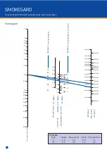
Page 10: ...PE B TYPE A SOUND LEVEL dbA GRILLE TOTAL PRESSURE N m 2 JET VELOCITY 200x100 250x100 300x100 350x100 200x200 400x100 250x200 300x200 350x200 400x200 300x300 350x300 400x300 400x400 200x100 250x100 300x100 350x100 200x200 400x100 250x200 300x200 350x200 400x200 300x300 350x300 400x300 400x400 TYPE B TYPE A GRILLE SIZES Nomogram Example Type Volume Sound Level Jet Vel Pressure Drop A 0 2 36 2 8 14 B...

Page 11: ... from one face flange to the other through the door itself The combined assembly was placed vertically against one open side of a 1m3 furnace and then securely bolted to maintain an air seal between Test Results The duration of the test was 1 hour and only slight charring of the timber around the damper frame was apparent after this time At the end of the test the integrity and stability of both t...

Page 12: ...tro magnet When the electro magnet is deenergised it allows the stainless steel pin to move forward thus disengaging the rack which moves immediately to the closed position shutting the blade pack For Mode A units a 72 C Fusible link is mounted on pivot brackets on the two opposed action blades On failure of said fuse link blades are allowed to move in opposed directions synchronised and driven by...

Reviews: