background image

2-3 M.I.T.

Whether the system will work stably with the overclock/overvoltage settings you made is dependent on your overall 

system configurations. Incorrectly doing overclock/overvoltage may result in damage to CPU, chipset, or memory 

and reduce the useful life of these components. This page is for advanced users only and we recommend you 

not to alter the default settings to prevent system instability or other unexpected results.  (Inadequately altering 

the settings may result in system's failure to boot. If this occurs, clear the CMOS values and reset the board to 

default values.)


`

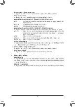
Advanced Frequency Settings 


&

CPU Base Clock


Allows you to manually set the CPU base clock in 0.01 MHz increments. (Default: Auto)


Important:

 It is highly recommended that the CPU frequency be set in accordance with the CPU 

specifications.


&

Host Clock Value


Displays the current operating Host Clock frequency.


&

IGP Ratio

 (Note)


Allows you to set the Graphics Ratio. (Default: Auto)


&

PCIe/DMI/PEG Clock Frequency


Allows you to manually set the host clock frequency (which controls CPU, PCIe, and memory frequencies) 

in 0.01 MHz increments.


&

CPU Clock Ratio


Allows you to alter the clock ratio for the installed CPU. The adjustable range is dependent on the CPU 

being installed.


&

CPU Frequency


Displays the current operating CPU frequency.


&

FCLK Frequency for Early Power On


Allows you to set the FCLK frequency. Options are: Normal(800Mhz), 1GHz, 400MHz. (Default: 1GHz)

(Note)  This item is present only when you install a CPU that supports this feature. For more information 

about Intel

®

 CPUs' unique features, please visit Intel's website.

- 24 -

Summary of Contents for W480M VISION W

Page 1: ...ming the packaging materials of this product are recyclable and reusable GIGABYTE works with you to protect the environment For more product details please visit GIGABYTE s website W480M VISION W User s Manual Rev 1001 12ME 480MVSW 1001R ...

Page 2: ... may be reproduced copied translated transmitted or published in any form or by any means without GIGABYTE s prior written permission In order to assist in the use of this product carefully read the User s Manual For product related information check on our website at https www gigabyte com Identifying Your Motherboard Revision The revision number on your motherboard looks like this REV X X For ex...

Page 3: ...talling an Expansion Card 11 1 6 Setting up AMD CrossFire Configuration 11 1 7 Back Panel Connectors 12 1 8 Internal Connectors 14 Chapter 2 BIOS Setup 22 2 1 Startup Screen 22 2 2 The Main Menu 23 2 3 M I T 24 2 4 System 32 2 5 Peripherals 33 2 6 Chipset 36 2 7 BIOS 38 2 8 Power 41 2 9 Save Exit 43 Chapter 3 Appendix 44 3 1 Configuring a RAID Set 44 3 2 Installing an Intel Optane Memory 46 3 3 Dr...

Page 4: ...5 One G Connector 5 5 User s Manual 5 5 Four SATA cables KB_MS_U32 HDMI DUAL_DP U32_LAN2 LGA1200 ATX AUDIO DDR4_A1 DDR4_A2 DDR4_B1 DDR4_B2 ATX_12V_2X4 Intel W480 CLR_CMOS M_BIOS PCIEX1_1 PCIEX8 PCIEX16 F_U32 CODEC W480M VISION W F_USB1 THB_C1 F_AUDIO F_USB2 COMA SPI_TPM F_PANEL SYS_FAN1 SYS_FAN2A CPU_FAN iTE Super I O M2A_SB 30 60 80 M2Q_CPU SATA3 7 5 6 4 BAT QFLASH_PLUS QFLED U32G2_LAN1 VGA Intel...

Page 5: ...ss x1 x1 DDR4 2933 2666 2400 2133 MHz DDI SPI Bus BIOS TPM x16 1 PCI Express x16 x8 2 PCI Express x8 Switch or HDMI 1 4 2 DisplayPorts D Sub LAN2 RJ45 x1 LAN1 RJ45 x1 Intel 2 5GbE LAN Intel GbE LAN 1 M 2 Socket 3 M2A_SB iTE Super I O 2 COM Ports LGA1200 CPU 1 M 2 Socket 3 M2Q_CPU Switch Center Subwoofer Speaker Out Line Out MIC Line In S PDIF Out Rear Speaker Out CODEC Intel W480 M 2 CNVi DDI ...

Page 6: ...a metal object to eliminate static electricity Prior to installing the motherboard please have it on top of an antistatic pad or within an electrostatic shielding container Before connecting or unplugging the power supply cable from the motherboard make sure the power supply has been turned off Before turning on the power make sure the power supply voltage has been set according to the local volta...

Page 7: ...cs Processor Intel HD Graphics support 1 x D Sub port supporting a maximum resolution of 1920x1200 60 Hz 1 x HDMI ports supporting a maximum resolution of 4096x2160 30 Hz Support for HDMI 1 4 version and HDCP 2 3 2 x DisplayPorts supporting a maximum resolution of 4096x2304 60 Hz Support for DisplayPort 1 4 version HDCP 2 3 and HDR Support for up to 3 displays at the same time Maximum shared memor...

Page 8: ...r 1 x CPU fan header 3 x system fan headers 8 x SATA 6Gb s connectors 2 x SATA detection headers 2 x M 2 Socket 3 connectors 1 x front panel header 1 x front panel audio header 1 x USB 3 2 Gen 1 header 2 x USB 2 0 1 1 headers 2 x Thunderbolt add in card connectors 1 x Trusted Platform Module header For the GC TPM2 0 SPI GC TPM2 0 SPI 2 0 module only 2 x serial port headers 1 x Clear CMOS jumper 1 ...

Page 9: ...lash Plus Support for Q Flash Support for Xpress Install Bundled Software Norton Internet Security OEM version cFosSpeed Operating System Support for Windows 10 64 bit Form Factor Micro ATX Form Factor 24 4cm x 24 4cm GIGABYTE reserves the right to make any changes to the product specifications and product related information without prior notice Please visit GIGABYTE s website for support lists o...

Page 10: ...he motherboard CPU socket and the notches on the CPU 1 4 Installing the Memory Read the following guidelines before you begin to install the memory Make sure that the motherboard supports the memory It is recommended that memory of the same capacity brand speed and chips be used Go to GIGABYTE s website for the latest supported memory speeds and memory modules Always turn off the computer and unpl...

Page 11: ...ing up AMD CrossFire Configuration Procedure and driver screen for enabling CrossFire technology may differ by graphics cards and driver version Refer to the manual that came with your graphics cards for more information about enabling CrossFire technology Note The bridge connector s may be needed or not depending on your graphics cards A System Requirements Windows 10 64 bit operating system A Cr...

Page 12: ...Gamut and High Dynamic Range HDR for Blu ray UHD playback You can use this port to connect your DisplayPort supported monitor Note The DisplayPort Technology can support a maximum resolution of 4096x2304 60 Hz but the actual resolutions supported depend on the monitor being used When removing the cable connected to a back panel connector first remove the cable from your device and then remove it f...

Page 13: ... 2 0 specification Use this port for USB devices Center Subwoofer Speaker Out Orange Use this audio jack to connect center subwoofer speakers Rear Speaker Out Black Use this audio jack to connect rear speakers Optical S PDIF Out Connector This connector provides digital audio out to an external audio system that supports digital optical audio Before using this feature ensure that your audio system...

Page 14: ...e power outlet to prevent damage to the devices After installing the device and before turning on the computer make sure the device cable has been securely attached to the connector on the motherboard 13 8 10 17 2 5 4 9 1 4 11 12 3 4 1 ATX_12V_2X4 2 ATX 3 CPU_FAN 4 SYS_FAN1 2A 2B 5 SATA3 0 1 2 3 4 5 6 7 6 SATA_SGP1 2 7 M2Q_CPU M2A_SB 8 F_PANEL 9 F_AUDIO 10 F_U32 11 F_USB1 F_USB2 12 SPI_TPM 13 THB_...

Page 15: ... GND 8 Power Good 20 NC 9 5VSB stand by 5V 21 5V 10 12V 22 5V 11 12V Only for 2x12 pin ATX 23 5V Only for 2x12 pin ATX 12 3 3V Only for 2x12 pin ATX 24 GND Only for 2x12 pin ATX ATX_12V_2X4 Pin No Definition Pin No Definition 1 GND Only for 2x4 pin 12V 5 12V Only for 2x4 pin 12V 2 GND Only for 2x4 pin 12V 6 12V Only for 2x4 pin 12V 3 GND 7 12V 4 GND 8 12V 3 4 CPU_FAN SYS_FAN1 2A 2B Fan Headers All...

Page 16: ...Configuration for more information SATA3 3 1 2 0 G QBOFM 1 7 1 7 G QBOFM G QBOFM 1 7 1 7 G QBOFM SATA3 7 5 6 4 6 SATA_SGP1 2 SATA Detection Headers The headers can connect to SATA detection devices Pin No Definition 1 NC 2 No Pin 3 DATA0 4 GND 5 GND 6 LOAD 7 NC 8 CLOCK _ B S B_ B _ S S_ _ B _ U _ B S 1 2 3 1 2 3 1 2 3 1 2 3 1 1 1 S _S S 3 B S S S U _ _ 3 F_USB3 F S F B_ B_ _ _ _ _B S _S _ S F_ B U...

Page 17: ...D into the connector at an angle Step 3 Press the M 2 SSD down and then secure it with the screw _ 0 F _ F B_ B30 3 _3 U 80 110 60 M2Q_CPU 42 _ 0 F _ F B_ B30 3 _ _3 U S _ 80 60 M2A_SB Installation Notices for the M 2 and SATA Connectors The availability of the SATA connectors may be affected by the type of device installed in the M 2 sockets The M2A_SB connector shares bandwidth with the SATA3 1 ...

Page 18: ...ont panel The LED is on when the hard drive is reading or writing data RES Reset Switch Green Connects to the reset switch on the chassis front panel Press the reset switch to restart the computer if the computer freezes and fails to perform a normal restart CI Chassis Intrusion Header Gray Connects to the chassis intrusion switch sensor on the chassis that can detect if the chassis cover has been...

Page 19: ...SB header can provide two USB ports via an optional USB bracket For purchasing the optional USB bracket please contact the local dealer Pin No Definition Pin No Definition 1 Power 5V 6 USB DY 2 Power 5V 7 GND 3 USB DX 8 GND 4 USB DY 9 No Pin 5 USB DX 10 NC Do not plug the IEEE 1394 bracket 2x5 pin cable into the USB 2 0 1 1 header Prior to installing the USB bracket be sure to turn off your comput...

Page 20: ...CMOS values by removing the battery 1 Turn off your computer and unplug the power cord 2 Gently remove the battery from the battery holder and wait for one minute Or use a metal object like a screwdriver to touch the positive and negative terminals of the battery holder making them short for 5 seconds 3 Replace the battery 4 Plug in the power cord and restart your computer Always turn off your com...

Page 21: ...e the BIOS settings refer to Chapter 2 BIOS Setup for BIOS configurations Open Normal Short Clear CMOS Values QFLED 17 QFLASH_PLUS Q Flash Plus Button Q Flash Plus allows you to update the BIOS when your system is off S5 shutdown state Save the latest BIOS on a USB thumb drive and plug it into the Q Flash Plus port and then you can now flash the BIOS automatically by simply pressing the Q Flash Pl...

Page 22: ...sion of BIOS from the Internet and updates the BIOS Chapter 2 BIOS Setup Because BIOS flashing is potentially risky if you do not encounter problems using the current version of BIOS it is recommended that you not flash the BIOS To flash the BIOS do it with caution Inadequate BIOS flashing may result in system malfunction It is recommended that you not alter the default settings unless you need to...

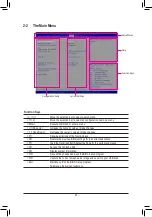
Page 23: ...w descriptions of the function keys F5 Restore the previous BIOS settings for the current submenus F7 Load the Optimized BIOS default settings for the current submenus F8 Access the Q Flash utility F9 Display system information F10 Save all the changes and exit the BIOS Setup program F12 Capture the current screen as an image and save it to your USB drive Esc Main Menu Exit the BIOS Setup program ...

Page 24: ...s Default Auto Important It is highly recommended that the CPU frequency be set in accordance with the CPU specifications Host Clock Value Displays the current operating Host Clock frequency IGP Ratio Note Allows you to set the Graphics Ratio Default Auto PCIe DMI PEG Clock Frequency Allows you to manually set the host clock frequency which controls CPU PCIe and memory frequencies in 0 01 MHz incr...

Page 25: ... d d Active Turbo Ratios Turbo Ratio Allows you to set the CPU Turbo ratios for different number of active cores Auto sets the CPU Turbo ratios according to the CPU specifications This item is configurable only when Active Turbo Ratios is set to Enabled Default Auto Intel R Turbo Boost Max Technology 3 0 Driver Note Enables or disables Intel Turbo Boost Max Technology 3 0 Intel Turbo Boost Max Tec...

Page 26: ...de in system halt state When enabled the CPU core frequency and voltage will be reduced during system halt state to decrease power consumption The C6 C7 state is a more enhanced power saving state than C3 Auto lets the BIOS automatically configure this setting This item is configurable only when C States Control is set to Enabled Default Auto C8 State Support Note Allows you to determine whether t...

Page 27: ...ne whether to enable hardware prefetcher to prefetch data and instructions from the memory into the cache Default Auto Adjacent Cache Line Prefetch Allows you to determine whether to enable the adjacent cache line prefetch mechanism that lets the processor retrieve the requested cache line as well as the subsequent cache line Default Auto Extreme Memory Profile X M P Note 2 Allows the BIOS to read...

Page 28: ...memory is not installed in the optimal memory channel Default Enabled Profile DDR Voltage When using a non XMP memory module or Extreme Memory Profile X M P is set to Disabled the value is displayed according to your memory specification When Extreme Memory Profile X M P is set to Profile1 or Profile2 the value is displayed according to the SPD data on the XMP memory Memory Multiplier Tweaker Prov...

Page 29: ...n for the CPU Vcore voltage CPU Vcore PWM Switch Rate Allows you to set the PWM frequency for the CPU Vcore voltage The adjustable range is from 300 0KHz to 500 0KHz Default Auto VAXG PWM Switch Rate Allows you to set the PWM frequency for the CPU VAXG voltage The adjustable range is from 300 0KHz to 500 0KHz Default Auto CPU Core Voltage Control This section provides CPU voltage control options C...

Page 30: ...trol the fan speed under the Fan Speed Percentage item Full Speed Allows the fan to run at full speeds Fan Speed Percentage Allows you to control the fan speed This item is configurable only when CPU Fan Speed Control is set to Manual Options are 0 75 PWM value o C 2 50 PWM value o C Fan Control Use Temperature Input Allows you to select the reference temperature for fan speed control Default CPU ...

Page 31: ...r system requirements Default Silent Allows the fan to run at slow speeds Manual Allows you to control the fan speed under the Fan Speed Percentage item Full Speed Allows the fan to run at full speeds Fan Speed Percentage Allows you to control the fan speed This item is configurable only when System 2 Fan Speed Control is set to Manual Options are 0 75 PWM value o C 2 50 PWM value o C Fan Control ...

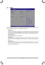
Page 32: ...BIOS settings the User level only allows you to make changes to certain BIOS settings but not all System Language Selects the default language used by the BIOS System Date Sets the system date The date format is week read only month date and year Use Enter to switch between the Month Date and Year fields and use the Page Up or Page Down key to set the desired value System Time Sets the system time...

Page 33: ...network card instead of using the onboard LAN set this item to Disabled Intel Platform Trust Technology PTT Enables or disables Intel PTT Technology Default Disabled Intel Trusted Execution Technology Note Enables or disables Intel Trusted Execution Technology Intel TXT Intel Trusted Execution Technology provides a hardware based security foundation Default Disabled Software Guard Extensions SGX E...

Page 34: ...ted USB mass storage devices This item appears only when a USB storage device is installed Network Stack Configuration Network Stack Disables or enables booting from the network to install a GPT format OS such as installing the OS from the Windows Deployment Services server Default Disabled IPv4 PXE Support Enables or disables IPv4 PXE Support This item is configurable only when Network Stack is e...

Page 35: ... Controller Interface AHCI is an interface specification that allows the storage driver to enable advanced Serial ATA features such as Native Command Queuing and hot plug Default Aggressive LPM Support Enables or disables the power saving feature ALPM Aggressive Link Power Management for the Chipset SATA controllers Default Disabled Port 0 1 2 3 4 5 6 7 Enables or disables each SATA port Default E...

Page 36: ...udio Controller Enables or disables the onboard audio function Default Enabled If you wish to install a 3rd party add in audio card instead of using the onboard audio set this item to Disabled Above 4G Decoding Enables or disables 64 bit capable devices to be decoded in above 4 GB address space only if your system supports 64 bit PCI decoding Set to Enabled if more than one advanced graphics card ...

Page 37: ...s Enables or disables this function Default Enabled Aperture Size Allows you to set the maximum amount of system memory that can be allocated to the graphics card Default 256MB BIOS Guard Enables or disables the Intel BIOS Guard feature which protects the BIOS from malicious attacks Default Disabled 37 ...

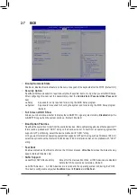
Page 38: ...erall boot order from the available devices Removable storage devices that support GPT format will be prefixed with UEFI string on the boot device list To boot from an operating system that supports GPT partitioning select the device prefixed with UEFI string Or if you want to install an operating system that supports GPT partitioning such as Windows 10 64 bit select the optical drive that contain...

Page 39: ...Disables booting from the network Default Enabled Enables booting from the network This item is configurable only when Fast Boot is set to Enabled or Ultra Fast Next Boot After AC Power Loss Normal Boot Enables normal bootup upon the return of the AC power Default Fast Boot Keeps the Fast Boot settings upon the return of the AC power This item is configurable only when Fast Boot is set to Enabled ...

Page 40: ...ssword allows you to make changes to all BIOS settings User Password Allows you to configure a user password Press Enter on this item type the password and then press Enter You will be requested to confirm the password Type the password again and press Enter You must enter the administrator password or user password at system startup and when entering BIOS Setup However the user password only allo...

Page 41: ...is set to Enabled Default Disabled Power On By Keyboard Allows the system to be turned on by a PS 2 keyboard wake up event Note To use this function you need an ATX power supply providing at least 1A on the 5VSB lead Disabled Disables this function Default Password Set a password with 1 5 characters to turn on the system Keyboard 98 Press POWER button on the Windows 98 keyboard to turn on the syst...

Page 42: ...rmines whether to power on the system at a desired time Default Disabled If enabled set the date and time as following Wake up day Turn on the system at a specific time on each day or on a specific day in a month Wake up hour minute second Set the time at which the system will be powered on automatically Note When using this function avoid inadequate shutdown from the operating system or removal o...

Page 43: ...the device you select and select Yes to confirm Your system will restart automatically and boot from that device Save Profiles This function allows you to save the current BIOS settings to a profile You can create up to 8 profiles and save as Setup Profile 1 Setup Profile 8 Press Enter to complete Or you can select Select File in HDD FDD USB to save the profile to your storage device Load Profiles...

Page 44: ...oller s is enabled To create RAID set SATA Mode Selection to Intel RST Premium With Intel Optane System Acceleration Note When using a PCIe SSD make sure to set the Use RST Legacy OROM item under Peripherals SATA And RST Configuration to Disabled and RST Control PCIe Storage Devices to Manual Then depending the M 2 connector you use set the corresponding PCIe Storage Dev on Port XX item to RST Con...

Page 45: ...array Skip this step and proceed with the installation of Windows operating system for a non RAID configuration Steps 1 In BIOS Setup go to BIOS and set CSM Support to Enabled and Storage Boot Option Control to Legacy Next go to Peripherals SATA And RST Configuration and make sure USE RST Legacy OROM is set to Enabled Save the changes and exit BIOS Setup After the POST memory test begins and befor...

Page 46: ... the Start menu and make sure the Intel Optane Memory has been enabled The SATA controller mode is changed to Intel RST Premium With Intel Optane System Acceleration from AHCI mode DO NOT change your SATA controller mode back to AHCI Doing so will cause the Optane memory unable to function properly 4 Ifyouwanttoacceleratethesystemdrive youcanselectspecificfolders files orapplicationstoaccelerateus...

Page 47: ... memory please select which one you are going to use Then select which drive to be accelerated Click Enable Follow the on screen instructions to proceed When completed restart the system 5 Launch the Intel Rapid Storage Technology utility from the Start menu and make sure the Intel Optane Memory has been enabled If you want to accelerate the system drive you can select specific folders files or ap...

Page 48: ...r double click the optical drive and execute the Run exe program Xpress Install will automatically scan your system and then list all of the drivers that are recommended to install You can click the Xpress Install button and Xpress Install will install all of the selected drivers Or click the arrow icon to individually install the drivers you need 3 3 Drivers Installation Please visit GIGABYTE s w...

Page 49: ... the product or on its packaging which indicates that this product must not be disposed of with other waste Instead the device should be taken to the waste collection centers for activation of the treatment collection recycling and disposal procedure For more information about where you can drop off your waste equipment for recycling please contact your local government office your household waste...

Page 50: ... 50 ...

Page 51: ... 51 ...

Page 52: ...8912 4000 FAX 886 2 8912 4005 Tech and Non Tech Support Sales Marketing https esupport gigabyte com WEB address English https www gigabyte com WEB address Chinese https www gigabyte com tw GIGABYTE eSupport To submit a technical or non technical Sales Marketing question please link to https esupport gigabyte com 52 ...

Reviews: