7
6
ENGLISH
Before
You Begin
7
6
Off
System is powered off, or in
Hibernate
mode.
On
System is in full operation.
Blinking
System is in
Standby
mode.
Note:
The
Five
System
LEDs
are located near the bottom of
display panel. For exact location, please refer to the
Top
View
diagram in
Chapter 1.2
.
For more details on
Standby
and
Hibernate
, please refer to
Power
Options
in the
Control
Panel
of your Microsoft Windows™
operating system.
Ø
Fn Keys
×
By pressing the Fn keys with other keys, it can simulate all
keyboard functions of a regular desktop keyboard.
[Fn]+[A]: Increase screen brightness.
[Fn]+[Z]: Decrease screen brightness.
[Fn]+[S]: Switch between LCD or external display device.
1.4 The Three Control Switches
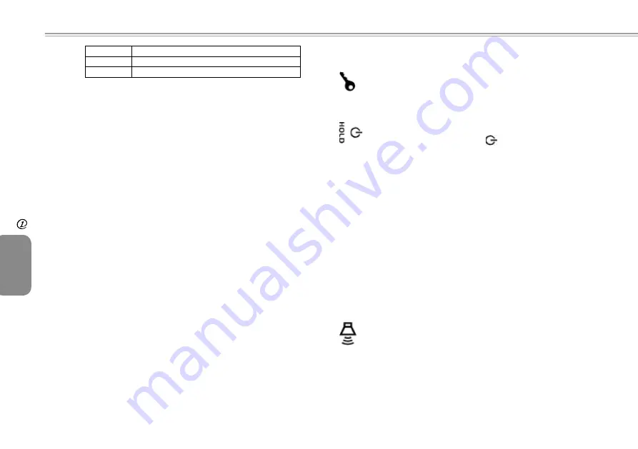
The SAS (Alt+Ctrl+Del) Switch
Press this switch to emulate Windows' "Alt", "Ctrl" and
"Del" buttons pressed simultaneously.
The Power/Hold Switch
Slide this switch to the right (
) to emulate standard
power button of a personal computer. The power button
is programmable by user. For details on how to program
the power button, please refer to the
Power Options
of
Control Panel
in
Windows™
System.
Slide this switch to the left
(HOLD)
to temporarily
suspend inputs from the
keyboard
,
touch pad
,
six
system buttons
on the left side of the LCD screen,
and the
four communication buttons
in between the
left/right keyboard. Manually slide this switch back to the
middle to resume functions of the above input devices.
The purpose of this switch is to prevent mis-triggering
of these input devices while the system unit is idle when
it is powered up. For exact locations of these input
devices, please refer to
Top View
diagram in
Chapter 1.2
.
The Volume Switch
Click this switch to the right (
┿
) to increase audio volume.
Click this switch to the left (
━
) to decrease audio volume.
Note:
The
Three
Control
Switches
is located on the right side
of system unit. For exact location, please refer to the
Right
View
diagram in
Chapter 1.2
.
Summary of Contents for U60 Ultra Mobile PC
Page 1: ...Ultra Mobile PC User s Guide Model U60 First Edition August 2007 ...
Page 4: ...IV ENGLISH IV ...
Page 14: ...10 ENGLISH Battery 10 Chapter 2 Battery ...
Page 22: ...18 ENGLISH The BAY Module Connector 18 Chapter 4 The BAY Module Connector ...
Page 26: ...22 ENGLISH Using the BIOS Setup Utility 22 Chapter 5 Using the BIOS Setup Utility ...
Page 28: ...24 ENGLISH Using the BIOS Setup Utility 24 The Main Menu Figure 5 1 Advanced Menu Figure 5 2 ...
Page 44: ...40 ENGLISH Recovery Update Notices 40 Appendix B Recovery Update Notices ...


