


System Appearance
- 16 -
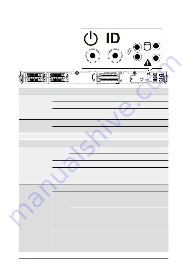
2-3 Front Panel LEDs and Buttons
No. Name
Color
Status
Description
1.
Power Button
with LED
Green
On
System is powered on
Green
Blink System is in ACPI S1 state (sleep mode)
N/A
Off
• System is not powered on or in ACPI S5 state (power off)
• System is in ACPI S4 state (hibernate mode)
2.
ID Button
with LED
Blue
On
System identification is active
N/A
Off
System identification is disabled
3.
Reset Button
N/A
N/A
Press this button to reset system
4.
NMI Button
N/A
N/A
Singal attention for non-recoverable hardware errors
5.
HDD Status
LED
Green
On
HDD locate
Blink HDD access
Amber
On
HDD error
Green /
Amber
Blink HDD rebuilding
N/A
Off
No HDD access or no HDD error
6.
System
Status LED
Green
On
System is operating normally
Amber
On
Critical condition, may indicate:
• System fan failure
• System temperature
Blink
Non-critical condition, may indicate:
• Redundant power module failure
• Temperature and voltage issue
• Chassis intrusion
N/A
Off
System is not ready, may indicate:
• POST error
• NMI error
• Processor or terminator is missing
NMI
NMI
1
2
3
4
5
6
Summary of Contents for T181-Z70
Page 1: ...T181 Z70 AMD EPYC 7003 server rack 1U 4 x GPU Card Slots User Manual Rev B00...
Page 37: ...37 System Hardware Installation 7 No Suggest Cable No Suggest Cable 7 HDD Backplane SATA Cable...
Page 40: ...System Hardware Installation 40 This page intentionally left blank...
Page 48: ...BIOS Setup 48 When Boot Mode Select is set to Legacy in the Boot Boot Mode Select section...
Page 59: ...59 BIOS Setup 5 2 8 PCI Subsystem Settings...
Page 70: ...BIOS Setup 70 5 2 17 Intel R Ethernet Controller X550...
Page 134: ...BIOS Setup 134 This page intentionally left blank...