


- 7 -
GH-PCU21-VG
English
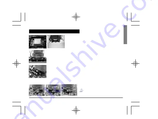
Figure 1
Figure 2
Figure 3
Figure 4
Figure 1
Please add an adequate layer of heat sink paste on the surface
of the CPU.
Figure 2
Figure showing the correct installation of the cooler atop the
CPU.
Figure 3
Align the three insert spaces of the clip with the three juts on the
CPU socket and then push firmly downwards to hold the clip in
space.
Figure 4
Push the lever on the side of the cooler towards the lever
position on the base of the CPU to secure the cooler atop the
CPU. Connect the yellow 3-pin connector cable of the
cooler to the CPU fan connector located on the motherboard.
Clip Installation is now complete.
Note: Please refer to page 8 & 9 for power
installation and installation of the fan speed
controller.
Installation Instructions for AMD Athlon 64 Clip


