background image

20190905 


5

4. Pin Assignment 

DC power jack


5. Operations 

Fat820w always creates a 

server

 and waiting for PC or other device building connection with TCP port 

(factory default is 

1001

). And fat820w also provide a 

client

 by Paragraph 

6-O 

command, trying to connect 

with server provide by host every 30 seconds. 


When you start up FAT820W, FAT820W will set the boot-up status from memory (EEPROM). Then sound 

a beep and LCD shows the start-up page. After that, FAT820W will stay at stand-by state. You can give a 
command to FAT820W. For example, show a message to direct customer to do some action (refer to Paragraph 

6-B

 command). You can also blink the LCD by Paragraph 

6-I

 command to attract the customer attention. 

You can press any key in the keypad. Please make sure keypad is enabled. If keypad is at “disable”, keypad 

doesn’t work. The power-up state is at “enable”. When you press the first key, the screen on LCD will be 
cleared, and the key will be shown on the left-top side. Following key-in will be left-to-right top-to-bottom 
showing on LCD by sequence. The key-in digits are 32 maximum. It will be ignored, if key-in digits over 32 
maximum. 

If LCD always show asterisk sign(*) when you press key. It means FAT820W is on “asterisk” displaying 

type. In fact, asterisk sign is just only for displaying. Real key is as the same as you pressed. You can change 
displaying type as “normal” type by Paragraph 

6-G

 command. Then the LCD displaying will show what you 

are pressing. 

The FAT820W have 2 operation modes. One mode is Un-Buffer mode. When you press one key, 

FAT820W send out that key(ASCII) by ETHERNET interface immediately. And the other one is Buffer mode. 
It will be kept in buffer, when you press keys, it will not send out all keys(ASCII) in the buffer by 
ETHERNET interface until you press ENTER and then the key-in digits on LCD will be erased. The buffer 
size is 32 maximum. It will be ignored, if key-in digits over buffer size 32 digits. 

Pin# 

Signal 

Center

(D2.1mm) +9V~+12VDC 

Outer 

GROUND 

Summary of Contents for FAT820W

Page 1: ...20190905 1 FAT820W Manual Version 1 3 Contents 1 Information 2 Introduction 3 Installation 4 Pin Assignment 5 Operations 6 Commands 7 Specification 8 FCC Statement ...

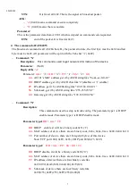
Page 2: ...ode of key position respectively One key can only map one symbol It will change what is your viewing type while you initialize device by command 6 H If you want to redefine the key value please see command 6 J 6 K Look Up Table for desktop viewing factory default KeyPos Symbol ASCII KeyPos Symbol ASCII KeyPos Symbol ASCII KeyPos Symbol ASCII 1 ESC 1BH 6 A 41H 11 B 42H 16 C 43H 2 1 31H 7 2 32H 12 3...

Page 3: ...20w has built 12 text pages to quickly show messages You just give the number of messages by Paragraph 6 B command FAT820w will show that message immediately If you want to show message directly or change messages in one of 12 text pages please refer to Paragraph 6 L command FAT820w has RFID reader reserved at the hardware Standard version do not build in If your FAT820w has RFID reader you can en...

Page 4: ...h to Wi Fi enable and then choose station mode 2 Plug in the DC power adaptor to the power jack on the FAT820W 3 Plug the adaptor to the power line 4 Waiting for connection of Wi Fi 5 Build connection with IP and Port shown at the screen C Wireless network AP Mode access point 1 Do Wi Fi setting by USB keyboard step and switch to Wi Fi enable and then choose ap mode 2 Plug in the DC power adaptor ...

Page 5: ...he screen on LCD will be cleared and the key will be shown on the left top side Following key in will be left to right top to bottom showing on LCD by sequence The key in digits are 32 maximum It will be ignored if key in digits over 32 maximum If LCD always show asterisk sign when you press key It means FAT820W is on asterisk displaying type In fact asterisk sign is just only for displaying Real ...

Page 6: ...rt you typing key and send text message will meet your specific viewing but not the saved graphics message page For the saved graphics message we suggest you redraw and save it again Setting IP address and port number of device Setting network parameters by command as following Ethernet Header 14 IP Header 20 UDP Header 8 UDP command or response CRC After got the device IP and port we can operatio...

Page 7: ...e or 1 enable PP IP address get it by ASCII string like 192 168 100 121 SS Sub mask get it by ASCII string like 255 255 255 0 GG Gateway get it by ASCII string like 192 168 100 254 Command N Description This command is used to setup network config The parameter type 1 is DHCP enable mode Parameter type 2 is DHCP disable mode Parameter type1 DD mm TU DD DHCP enable it will be a binary code0x31 1 mm...

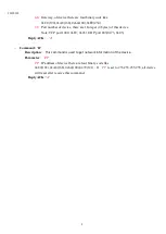
Page 8: ...this device Note TCP port 1001 0xE9 0x03 UDP port 883 0x73 0x03 Reply ACK A Command R Description This command is used to get network information of the device Parameter PP PP IP address of device there are four binary code like 0xC0 192 0xA8 168 0x64 100 0x79 121 If PP is set to 255 255 255 255 all device will reset after receive this command Reply ACK A ...

Page 9: ...at Description V STX V ETX Get device firmware version status D STX Dmn ETX Show pre saved message page on LCD C STX C ETX Erase LCD and buffer M STX Mn ETX Enable Disable reader K STX Kn ETX Enable Disable keypad B STX Bn ETX Control beep P STX Pmn ETX Change operation parameters STX ETX Initialize device F STX F ETX Blink the display I STX I n ETX Inquiry the keycode of key X STX X m n ETX Defin...

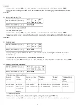
Page 10: ...ault text page table Page Message Page Message Page Message 1 Welcome 5 Card error 9 Verify fail 2 Enter PIN 6 Press ENT 10 Re enter PIN 3 PIN error 7 Time out 11 Thank you 4 Swipe card 8 Please try again 12 Not working C Erase LCD and buffer HOST to DEVICE 3 bytes STX C ETX 02H 43H 03H DEVICE to HOST 1 bytes ACK NACK You can clear all screen and buffer by this command Device will reply ACK if thi...

Page 11: ...ng composed of 0and 1 Each 1 will activate buzzer 0 will stop buzzer Each bit control buzzer 0 1 sec For example n F5H 11110101 it sounds like BBBB B B Device will reply ACK and beep if this command is acknowledged Otherwise reply NACK G Change Operation parameters HOST to DEVICE 5 bytes STX P m n ETX 02H 50H bin bin 03H DEVICE to HOST 1 bytes ACK NACK Parameter description as below Keypad m 31H M...

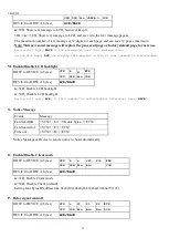
Page 12: ... the device is interrupted by next operation like communication key in etc Device will reply ACK if this command is acknowledged Otherwise reply NACK J Inquiry the keycode of key HOST to DEVICE 4 bytes STX I n ETX 02H 49H Bin 03H DEVICE to HOST 1 bytes Keyvalue ACK Or NACK Inquiry what is the keycode K Define the keycode of keys HOST to DEVICE 5 bytes min STX X m n ETX 02H 58H bin bin 03H DEVICE t...

Page 13: ... HOST to DEVICE 4 bytes STX b n ETX 02H 62H Bin 03H DEVICE to HOST 1 bytes ACK NACK n 31H Enable LCD backlight n 30H Disable LCD backlight Device will reply ACK if this command is acknowledged Otherwise reply NACK N Notice Message Notice Message is Device to send a notice to host automatically O Enable Disable Client mode HOST to DEVICE 4 bytes STX R n P0 P3 ETX 02H 52H Bin Bin 03H DEVICE to HOST ...

Page 14: ...sired operation FEDERAL COMMUNICATIONS COMMISSION INTERFERENCE STATEMENT This equipment has been tested and found to comply with the limits for a Class B digital device pursuant to Part 15 of the FCC Rules The limits are designed to provide reasonable protection against harmful interference in a residential installation This equipment generates uses and can radiate radio frequency energy and if no...

Page 15: ...e changes or modifications not expressly approved by the party responsible for compliance could void the user s authority to operate the equipment RF exposure warning This equipment must be installed and operated in accordance with provided instructions and the antenna s used for this transmitter must be installed to provide a separation distance of at least 20 cm from all persons and must not be ...

Reviews: