Hardware Installation
- 27 -
Chapter 3 System Appearance
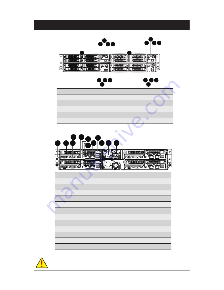
3-1 Front View
No.
Decription
1
ID button and LED
2.
Power button and LED
3.
VGA port
4.
USB 3.0 ports
5.
HDD bays
3-2 Rear View
No.
Decription
1
VGA port
2.
PCIe slot cover
3.
Serial port
4.
Power button and LED
5.
ID Button and LED
6.
BMC Reset button (top)/NMI button (bottom)
7.
System Status LED
8.
LAN ports
9.
10/100 Server management LAN port
10.
USB 2.0 ports
11.
Power supply fan
12.
Power supply module cord socket
NOTE!
For detail LED description, please see the following section:
Front Panel LED and Buttons
and
Rear System LEDs and Button
.
1 2
3
4
4
5
5
2
1
3
1 2
3
4
4 2
1
3
1
6
3
2
7 8
9
10 11 12
4 5
Summary of Contents for GS-R22PDP
Page 24: ... 24 Hardware Installation ...
Page 28: ... 28 Hardware Installation 3 3 HDD and Nodes Connection 4 2 1 3 ...
Page 47: ...BIOS Setup 47 5 2 3 CPU Configuration ...
Page 54: ... 54 BIOS Setup 5 2 6 SATA Configuration ...
Page 58: ... 58 BIOS Setup 5 2 9 Super IO Configuration ...
Page 60: ... 60 BIOS Setup 5 2 10 Serial Port Console Redirection ...
Page 65: ...BIOS Setup 65 5 2 13 Intel R I350 Gigabit Network Connection ...
Page 68: ... 68 BIOS Setup 5 3 1 North Bridge ...


