ON MODE
ATEST
SAFETY
STATE
ON
CAP R
Receiver output
CAP R
Receiver output
Optical safety
edge
power supply
ATEST
WORK MODE
SW4 at OFF
SW4 at OFF
Positive polarity
ATEST > 150ms
ATEST > 300ms
Ton
ATEST
Ton
safety state
Ton
ATEST
Ton
safety state
Safety activated
OK
NOT OK
OK
ON
OFF
GATE CONTROL PANEL
10
11
4 - CONNECTIONS
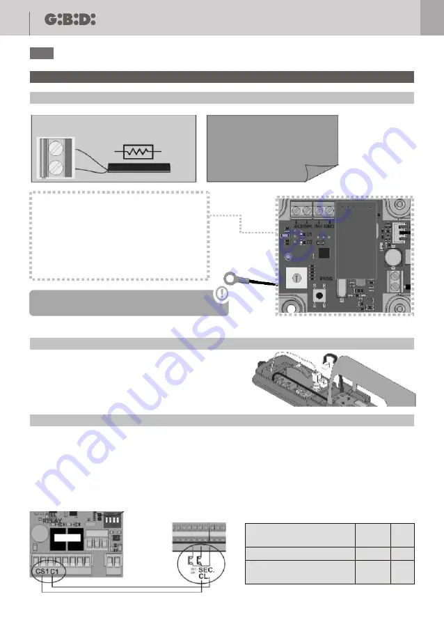
4.1 - CONNECTING THE CAP T (safety edge)
4.3 - CONNECTING THE RECEIVER TO THE CONTROL PANEL
8k2 RESISTIVE SAFETY EDGE
Supports 8k2/10k
resistive safety edges.
8k2/10k
INHibition input (N.O.) on the transmitter
works in the same way as inhibition input
on the receiver.
A closing signal in INH switches off the
NO-TOUCH sensor.
Ground cable must be fixed to the gate.
Make sure that ground and antenna wires
are NOT in contact.
Connecting the safety outputs to gate control panel:
The equipment can be connected to the gate control panel to any input for safety edge 8k2 or directly into a safety
input normally closed contact as if it were a photocell or stop signal.
This connectivity exists for R1 and R2 outputs.
In order to comply with EN ISO 13849-1: 2008 safety standard, a signal to test the system must be connected.
EXAMPLE: connection to gate control panel with safety contact / STOP input
EXAMPLE: connection to gate control panel with input for safety edge 8k2
Check the ground wire is properly fixed and the cable
tension is calibrated.
Any kind of external signal is suitable to manage the activation / deactivation of the NO TOUCH function. A dry
contact signal must be connected into INH – GND terminal. Selector 3 on the receiver selects the inhibition signal
polarity (NO or NC) to be able to apply different kind of signals.
When INH LED on the receiver is switched on, the NO TOUCH sensor is deactivated.
When working with optical safety edges, in ON mode, only OSE-S7502 are allowed as they remain always active.
The radio communication is tested every 7 or 30 seconds depending on the selector SW1 of the receiver.
In WORK mode, the ATEST signal is used to power up and down the optical safety edges. The radio communication
is tested as in ON mode and when the optical elements are powered up and down.
Safety edge status
R1
status
R1
LED
Safety edge activated or
not programmed
Safety edge OK
Close
OFF
Open
ON
CONTROL PANEL
Safety edge status
R1
status
R1
LED
Safety edge activated or
not programmed
Safety edge OK
OFF
ON
GATE CONTROL PANEL
4.2 - CONNECTING THE CAP ACTIVE (safety edge)
4.4 - CONNECTING MAGIN TO THE RECEIVER
CAPTIVE
CAPTIVE
EN
EN


