background image

25

BE24

ATTENTION: 

INSTRUCTIONS DE SÉCURITÉ.

IMPORTANTES 

Il est important pour la sécurité des personnes suivre ces instructions-ci.
Garder la présente notice d’instructions.

3  - INSTRUCTIONS POUR L’INSTALLATION

4 - MISES EN GARDE POUR L’UTILISATEUR

• En cas de panne ou dysfonctionnement, couper l’alimentation en amont de l’appareil et appeler l’assistence 

technique. Vérifier périodiquement le fonctionnement des dispositifs de sécurités. Les éventuelles réparations
doivent être exécutées par personnel spécialisé utilisant matériels d’origine et certifiés.

• Le produit ne doit pas être utilisé par enfants ou personnes avec réduites capacités physiques, sensoriales ou 

mentales, o sans expérience et connaissance, à moins qu’ils n’ont pas été correctement instruis.

• Ne pas accéder à la fiche pour régulations et/ou maintenances.

• Avant  d’effectuer  l’installation,  il  faut  prévoir  en  amont  de  la  même  un  interrupteur  magnétique 

thermique  et  différentiel  avec  capacité  maxi  10A.  L’interrupteur  doit  assurer  une  séparation  omnipolaire  des 
contacts, avec distance d’ouverture d’au moins 3 mm.

• Pour éviter possibles interférences, différencier et maintenir toujours séparés les câbles de puissance (section 

mini 1,5mm²) des câbles de signal (section mini 0,5mm²).

• Effectuer  les  connections  en  se  référant  aux  tableaux  suivants  et  à  la  sérigraphie  ci-jointe.  Il  faut  faire 

particulièrement attention à  raccorder  en  série  tous  les  dispositifs  qui  doivent  être  connectés  à  la  même  entrée 
N.C.  (normalement fermé) et en parallèle tous les dispositifs qui partagent la même entrée N.O. (normalement 
ouvert).

• Une mauvaise installation ou une mauvaise utilisation du produit peut compromettre la sécurité de l’installation.
• Tous  les  matériaux  présents  dans  l’emballage  ne  doivent  pas  être  laissés  à  la  portée  des  enfants  car  ils 

peuvent être dangereux.

• Le constructeur décline toute responsabilité quant au bon fonctionnement de l'automation en cas d’utilisation de 

composants et accessoires de sa production et inappropriés à l’utilisation prévue.

• Après  la  mise  en  place,  il  faut  toujours  contrôler  avec  attention  le  bon  fonctionnement  de  l’installation  et  des

dispositifs utilisés.

• Cette notice d’instructions s’adresse à personnes autorisées à la mise en place d’“appareils sous tension”, il faut 

donc  avoir  une  bonne  connaissance  de  la  technique,  exercée  comme  profession  et  conformément  aux
reglémentations en vigueur.

• La maintenance doit être effectuée par un personnel qualifié.
• Avant  d’effectuer  toute  opération  de  nettoyage  ou  maintenance,  il  faut  débrancher  la  platine  des  réseaux 

d’alimentation électrique.

• La platine ici décrite doit être utilisée uniquement pour l’emploi pour le quel elle a été conçue.
• Vérifier le but de l'utilisation finale et s’assurer de prendre toutes les sécurités nécessaires.
• L’utilisation  des  produits  et  leur  destination  à  des  usages  différents  de  ceux  prévus,  n’a  pas  été  expérimentée

par le constructeur,  donc  les  travaux  exécutés  sont  sous  l’entière  responsabilité  de  l’installateur.  Signaler
l’automation avec plaques de mise en garde qui doivent être visibles.

• Aviser l’usager que les enfante ou les animaux ne doivent pas jouer ou s’arrêter près du portail.
• Protéger d’une manière adéquate les points de danger (par exemple en utilisant une bande sensible).

FR

Summary of Contents for AS05870

Page 1: ...ica ISTRUZIONI PER L INSTALLAZIONE Electronic control unit INSTRUCTIONS FOR INSTALLATION Platine électronique INSTRUCTIONS POUR L INSTALLATION Equipo electrónico INSTRUCCIONES PARA LA INSTALACIÓN Elektronische besturing GEBRUIKSAANWIJZING VOOR DE INSTALLATIE ...

Page 2: ...redisposizione per uso con batterie tampone Soft Start e Soft Stop per limitare gli shock meccanici 2 possibili logiche di funzionamento passo passo con stop o condominiale selezionabile tramite dip switch Tempo sfasamento ante regolabile tramite dip switch 2 CARATTERISTICHE TECNICHE FUNZIONI 1 CARATTERISTICHE TECNICHE BE24 AS05870 230 Vac monofase 50 60 Hz 2 24 Vdc 24 Vdc 10W max Integrato massim...

Page 3: ...o dell impianto e dei dispositivi utilizzati Questo manuale d istruzioni si rivolge a persone abilitate all installazione di apparecchi sotto tensione pertanto si richiede una buona conoscenza della tecnica esercitata come professione e nel rispetto delle norme vigenti La manutenzione deve essere eseguita da personale qualificato Prima di eseguire qualsiasi operazione di pulizia o di manutenzione ...

Page 4: ... PHOTO 2 21 Comune ingressi 22 COM 23 5 COLLEGAMENTI ELETTRICI FASTON Descrizione CF1 0 Vac da trasformatore FASTON 24 Vac da trasformatore Comune ingressi COM Ingresso FOTOCELLULA 1 N C attiva solo in chiusura Quando viene intercettata durante la chiusura inverte immediatamente il moto in apertura In apertura è ininfluente Inpausaricaricailtempodipausa CF2 M2 IngressoFOTOCELLULA2 N C attivainaper...

Page 5: ...OTO2 L5 ROSSO SAFETY Sempre acceso si spegne quando viene rilevato un valore non corretto sul morsetto SAFETY L6 ROSSO RX SEMPRE spento Si accende quando viene premuto il pulsante LEARN per memorizzare un nuovo TX o per cancellare tutti i TX L7 BLU INFO 0 2s ON 0 2 OFF La centrale è bloccata in attesa di effettuare il ciclo di apprendimento E necessarioeseguireilciclodiapprendimento 30s ON La cent...

Page 6: ... APRE OFF ON MORSETTO 21 COME COSTA 8K2 Funzionamento ŸCancellochiuso ŸDurantel apertura STOP ŸCancelloaperto STOP norichiusuraautomatica ŸDurantelachiusura STOP ŸDopouno STOP inverteilmoto ININFLUENTE Funzionamento ŸCancello chiuso ININFLUENTE ŸDurante l apertura Inversione immediata del moto per 2s rallentando e a liberazione del contatto inversione totale con moto rallentato ŸCancelloaperto INI...

Page 7: ...vorire lo sgancio dell elettroserratura Funzionamento al comando di START si avrà in sequenza attivazione dell elettroserratura impulso in chiusura di 1 s apertura dopo 2 s sgancio dell elettroserratura ON OFF 10 DIP SWITCH DIP2 Le impostazioni vengono memorizzate durante la fase di riposo cancello chiuso Le impostazioni di DEFAULT sono evidenziate con lo sfondo della casella in grigio Velocità ra...

Page 8: ...ina l inversione immediata del moto in rallentamento per 1 secondo Dopounabrevissimapausailmotoproseguirànelversodiliberazioneconil correttosfasamentoeconmotoRALLENTATO N 3 interventi consecutivi oltre i quali l automazione si blocca e sarà richiesto un comandodell utenteperriprendereilmoto Nonattivoseilfunzionamentoèatempo DIP2_4 OFF 2_5 Anti schiacciamento escluso ON ANTI SCHIACCIAMENTO OFF 2_6 ...

Page 9: ...N Ingresso associato al pulsante 4 del trasmettitore PED Se l impostazione è uguale a DIP3_1 e DIP3_2 il PEDONALEèdisabilitato 3_5 OFF INUTILIZZATO 3_6 ON OFF INUTILIZZATO Tenere OFF non modificare 12 GESTIONE RICEVENTE RADIO A BORDO Memorizzazione nuovo trasmettitore 1 Premere e rilasciare il pulsante Learn 2 Il led L6 si accenderà 3 Premere il tasto 1 del radiocomando da memorizzare per 2 second...

Page 10: ...ere con il pulsante MEMO il tipo di motore da utilizzare La prima pressione del pulsante attiverà la selezione del motore KUDA AGO424 624 e il led L7 farà un lampeggio la seconda pressione del pulsante MEMO attiverà la scelta del motore SERRA320 e il led L7 farà due lampeggi La sequenza continuerà ciclicamente ad ogni pressione del pulsante MEMO Ora premere il tasto 1 START del radiocomando o dare...

Page 11: ...to con le sole batterie In apertura il cancello si muove piano Durante la prima manovra dopo aver alimentato la centrale il moto in aperturasaràavelocitàrallentataedinmodalitàcondominiale Significato Segnalazione Effetto Fotocellula 2 intercettata a riposo in presenza di comando di START Costa intercettata a riposo in presenza di comando di START Costa intercettata in pausa in presenza di comando ...

Page 12: ...e i prodotti APPARECCHIATURA ELETTRONICA BE24 sono conformi alle seguenti Direttive CEE e che sono state applicate le seguenti norme armonizzate Data 01 08 2017 S r l DirettivaLVD2006 95 CE esuccessivemodifiche DirettivaEMC2004 108 CEesuccessivemodifiche EN60335 1 EN61000 6 2 EN61000 6 3 Il Rappresentante Legale Michele Prandi IT ...

Page 13: ...ble via DIP switch Programming of automatic closing and pause time via DIP switch Provision for use with buffer batteries Soft Start and Soft Stop to limit mechanical shock 2 TECHNICAL SPECIFICATIONS FUNCTIONS 1 TECHNICAL SPECIFICATIONS BE24 AS05870 230 VAC single phase 50 60 Hz 2 24 Vdc 24 Vdc 10W max Integrated 200 trasmitters maximum 20 C 60 C ENCODER or TIME 24 Vdc 10W max Electronic control u...

Page 14: ...e N C normally closed input and in parallel all the devices that share the same N O normally open input Incorrect installation or improper use of the product may compromise system safety Keep all the materials contained in the packaging away from children since they pose a potential hazard The manufacturer declines all responsibility for improper functioning of the automated device if the original...

Page 15: ...ply 14 5V Motor 2 ENCODER signal 15 S2 Motor 2 ENCODER power and signal common 16 COM M4 START input N O 17 START PEDESTRIAN input N O 18 PED 19 PHOTO 1 20 PHOTO 2 21 Accessory common 22 COM 23 Accessory common COM PHOTOCELL 1 input N C Input active only during closing It stops and inverts the motion opening the gate completely If the gate is closed it does not affect its functioning Ifintercepted...

Page 16: ...s off when the contact of terminal PHOTO 2 is opened L5 RED SAFETY Always on Comes off when the resistance value of terminal SAFETY is wrong L6 RED RX Always off comes on when LEARN button is pressed L7 BLUE INFO 0 2s ON 0 2 OFF The control board is locked it s necessary to execute a new travel learningprocedure 30s ON The control board is in pre learning phase aftre pressing MEMO button 0 2s ON 4...

Page 17: ...ringclosing STOP Operation Ÿ ŸDuringopening Immediate motion inversion for 2s at low speed when contactisfreed thegatewillcontinuewithinvertedmovementatlowspeed ŸGateopen UNINFLUENTIAL ŸDuringclosing Immediate motion inversion for 2s at low speed when contactisfreed thegatewillcontinuewithinvertedmovementatlowspeed Gate closed UNINFLUENTIAL 1_1 1_2 TERMINAL 21 AS 8K2 STOP 1_3 1_4 ANTI CRUSHING SEN...

Page 18: ...Operation at the START command the following will occur in sequence electric lock activation closing pulse of 1 sec opening electric lock release after 2 sec ON OFF 10 DIP SWITCH DIP2 Decelerationspeedequalto50 ofthemaximumspeed 2_1 Decelerationspeedequalto30 ofthemaximumspeed ON DECELERATION SPEED OFF Speedduringnormalmovementequalto100 ofthemaximumspeed 2_2 Speedduringnormalmovementequalto80 oft...

Page 19: ...3 consecutive anti crushing interventions the control board will STOPandausercommandwillberequiredtostartagainthemotion Anticrushingisnotactivewhenworkingbytime DIP2_4 OFF 2_5 Anticrushingdisabled ON ANTI CRUSHING OFF 2_6 ON OFF 2_7 ON OFF 2_8 ON OFF 2_9 ON OFF 2_10 ON OFF SPIA FLASHING LIGHT UNUSED UNUSED UNUSED UNUSED Terminal M2_7 and M2_8 work as WARNING LIGHT Terminal M2_7 and M2_8 work as FL...

Page 20: ... boxes with grey background Transmitter button 1 Transmitter button 2 Transmitter button 3 Transmitter button 4 12 ONBOARD RADIO RECEIVER CONTROL Storing a new transmitter in memory 1 Press and release Learn button 2 Led L6 will come on 3 Press button 1 of the transmitter to be stored for 2 seconds 4 The new transmitter is stored 5 Led L6 will stay on for another 5 seconds during this period you c...

Page 21: ... 30 seconds press again MEMO button in order to choose operator type At the first stroke L7 will blink once every 4 seconds and that means KUDA AGO424 624 is the installed operator at the second stroke L7 will blink twice every 4 seconds and that means SERRA320 is the installed operator The operator selection sequence is cyclic Press button 1 of the radio control or give a START pulse from the ter...

Page 22: ... a START command Ÿ Check that L3 L4 and L5 are off if not check the devices connected to terminals19 20 21 Ÿ Checkfuses Ÿ Checkthatthebatteryvoltageisnotbelow22VDC Ÿ IfL7isblinkingfast learningproceduremustbeexecuted The gate moves slowly during opening The first maneuvre after a power failer is slowed and with automatic logic The gate does not fully open close Check the motor and encoder connecti...

Page 23: ...llowing CEE Directives and that the following harmonised standards have been applied GI BI DI Via Abetone Brennero 177 B 46025 Poggio Rusco MN ITALY d Date 01 08 2017 S r l DirectiveLVD2006 95 CE andsubsequentamendments DirectiveEMC2004 108 CEandsubsequentamendments EN60335 1 EN61000 6 2 EN61000 6 3 The legal Representative Michele Prandi ...

Page 24: ...ip switch Arrêt et inversion du mouvement après l intervention des dispositifs de sécurité Fonction anti écrasement tant à vitesse normale qu à vitesse ralentie Lecture ampère métrique de l absorption du moteur pour la fonction anti écrasement réglable par dip switch Fonctionnement piéton avec ouverture porte 1 2 entrées N C photocellule 1 photocellule 2 1 Entrée SAFETY 8K2 programmable par dip sw...

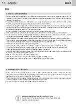
Page 25: ...tagent la même entrée N O normalement ouvert Une mauvaise installation ou une mauvaise utilisation du produit peut compromettre la sécurité de l installation Tous les matériaux présents dans l emballage ne doivent pas être laissés à la portée des enfants car ils peuvent être dangereux Le constructeur décline toute responsabilité quant au bon fonctionnement de l automation en cas d utilisation de c...

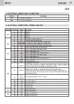
Page 26: ...entrées 22 COM 23 5 BRANCHEMENTS ELECTRIQUES FASTON Description CF1 0 Vac de transformateur FASTON 24 Vac de transformateur Commun entrées COM Entrée PHOTOCELLULE 1 N C active seulement en fermeture Quand elle est interceptée pendant la fermeture elle inverse tout de suite le mouvement en ouverture Enouvertureellen estpasinfluente Enpauseellerechargeletempsdepause CF2 M2 EntréePHOTOCELLULE2 N C ac...

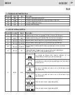
Page 27: ...ROUGE SAFETY Toujours allumé s éteint quand on relève une valeur pas correct sur la borne SAFETY L6 ROUGE RX TOUJOURS éteint S allume quand on appuie sur la touche LEARN pour mémoriser un nouveau TX ou pour effacer tous les TX L7 BLEU INFO 0 2s ON 0 2 OFF La centrale est bloquée dans l attente d effectuer le cycle d apprentissage Ilfautfairelecycled apprentissage 30s ON La centrale est en phase de...

Page 28: ...F ON BORNE 21 COMME BORD SENSIBLE 8K2 Fonctionnement ŸPortailfermé ŸPendantl ouverture STOP ŸPortailouvert STOP pasderefermetureautomatique ŸPendantlafermeture STOP Ÿ AprèsunSTOP inverselemouvement PASINFLUENT Fonctionnement ŸPortail fermé PAS INFLUENT ŸPendant l ouverture Inversion immédiate du mouvement par 2s ralentissant et après liberation du contact inversion totale avec mouvement ralenti ŸP...

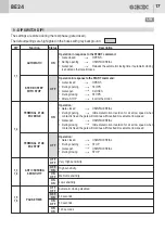
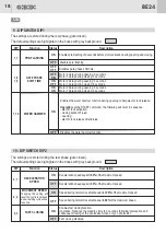
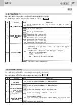
Page 29: ...rochage de la serrure électrique Fonctionnement à la commande de START il y aura en séquence activation de la serrure électrique impulsion en fermeture de 1 s ouverture après 2 s décrochage de la serrure électrique ON OFF 10 DIP SWITCH DIP2 Les positions sont mémorisées pendant la phase de repos portail fermé Les positions par DEFAUT sont indiquées dans la case grise Vitesse ralentissement égale a...

Page 30: ...ent en ralentissement par 1 s Après une pause très brève le mouvement continuera dans le sens de libérationaveccorrectdéphasageetmouvementRALENTI N 3 interventions consécutives après les quelles l automation se bloquera y une commandedel usagerserademandépourreprendrelemouvement Pasactifsilefonctionnementestàtemps DIP2_4 OFF 2_5 Anti écrasement exclu ON ANTI ECRASEMENT OFF 2_6 ON OFF 2_7 ON OFF 2_...

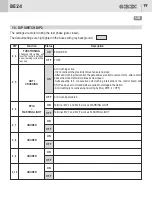
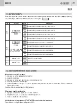
Page 31: ...N ON Entrée associée à la touche 4 de l émetteur PED Si la position est égale à DIP3_1 et DIP3_2 le PIETONestdésactivé 3_5 OFF PAS UTILISE 3_6 ON OFF PAS UTILISE Tenir OFF ne pas modifier 12 GESTION RECEPTEUR RADIO A BORD Mémoriser un nouvel émetteur 1 Appuyer sur la touche Learn et la relâcher 2 Le led L6 s allumera 3 Appuyer sur la touche 1 de l émetteur à mémoriser par 2 s 4 Le nouvel émetteur ...

Page 32: ...type de moteur qu on doit utiliser La première pression de la touche activera la sélection du moteur KUDA AGO424 624 et le led L7 fera un clignotement la deuxième pression de la touche MEMO activera la choix du moteur SERRA320 et le led L7 fera deux clignotements La séquence continuera cycliquement à chaque pression de la touche MEMO Maintenant appuyer sur la touche 1 START de l émetteur ou donner...

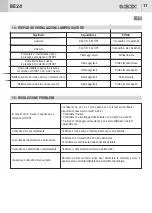
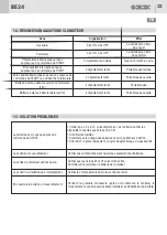
Page 33: ...ortail se mouve lentement Pendant la première manœuvre après avoir alimenté la centrale le mouvementenouvertureseraàvitesseralentieetenmodalitédecopropriété 14 RESUME SIGNALISATIONS CLIGNOTEUR Sens Signalisation Effet Photocellule 2 interceptée au repos en présence de commande de START Bord sensible intercepté au repos en présence de commande de START Bord sensible interceptée en pause en présence...

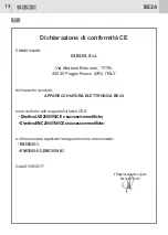
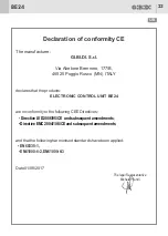
Page 34: ...ives CEE suivantes et que les normes harmonisées suivantes ont été appliquées GI BI DI Via Abetone Brennero 177 B 46025 Poggio Rusco MN ITALY d BE24 Date 01 08 2017 S r l DirectiveLVD2006 95 CEetmodificationssuccessives DirectiveEMC2004 108 CEetmodificationssuccessives EN60335 1 EN61000 6 2 EN61000 6 3 Le Représentant légal Michele Prandi ...

Page 35: ...posición para uso con baterías tampón Soft Start y Soft Stop para limitar los choques mecánicos 2 posibles lógicas de funcionamiento paso paso con stop o de copropiedad seleccionable por dip switch Tiempo desfase hojas regulable por dip switch 2 CARACTERISTICAS TECNICAS FUNCIONES 1 CARACTERISTICAS TECNICAS BE24 AS05870 230 Vac monofásico 50 60 Hz 2 24 Vdc 24 Vdc 10W max Integrado 200 transmisores ...

Page 36: ...teriales presentes en el embalaje deben mantenerse fuera del alcance de los niños ya que consituyen una posible fuente de peligro El fabricante declina toda responsabilidad relativa al correcto funcionamiento de la automatización si no se utilizan los componentes y accesorios de propia producción destinados a la aplicación prevista Al terminar la instalación comprobar siempre con atención el corre...

Page 37: ...HOTO 1 20 PHOTO 2 21 Común entradas 22 COM 23 5 CONEXIONES ELECTRICAS FASTON Descripción CF1 0 Vac desde transformador FASTON 24 Vac desde transformador Común entradas COM Entrada FOTOCELULA1 N C activa sólo en cierre Cuando es interceptada durante el cierre invierte de inmediato el movimiento en apertura En apertura no es influyente Enpausarecargaeltiempodepausa CF2 M2 EntradaFOTOCELULA2 N C acti...

Page 38: ...to del borne PHOTO2 L5 ROJO SAFETY Siempre encendido se apaga cuando se detecta un valor no correcto sobre el borne SAFETY L6 ROJO RX SIEMPRE apagado Se enciende cuando se apreta la tecla LEARN para memorizar un nuevo TX o para cancelar todos los TX L7 AZUL INFO 0 2s ON 0 2 OFF La central está bloqueada a la espera de efectuar el ciclo de aprendizaje Esnecesariohacerelciclodeaprendizaje 30s ON La ...

Page 39: ... 21 COMO BANDA SENSIBLE 8K2 Funcionamiento ŸCancelacerrada ŸDurantelaapertura STOP ŸCancelaabierta STOP norecierreautomático ŸDuranteelcierre STOP ŸDespuésdeun STOP invierteelmovimiento NOESINFLUYENTE Funcionamiento ŸCancela cerrada NO ES INFLUYENTE ŸDurante la apertura Inversión inmediata del movimiento por 2s decelerando y una vez liberado el contacto inversión total con movimiento decelerado ŸC...

Page 40: ...ecer el desenganche de la electrocerradura Funcionamiento al mando de START hay en secuencia activación de la electrocerradura empuje en cierre de 1 s apertura después de 2 s desensganche de la electrocerradura ON OFF 10 DIP SWITCH DIP2 Las posiciones son memorizadas durante la fase de reposo cancela cerrada Las posiciones por DEFECTO son evidenciadas por la casilla gris Velocidad deceleración igu...

Page 41: ...celeración por1segundo Despuésdeunabrevísimapausa elmovimientoseguiráenelsentido deliberaciónconelcorrectodesfaseyconmovimientoDECELERADO N 3 intervenciones consecutivas más allá de las cuales la automatización se bloqueayseránecesariounmandodelusuarioparareanudarelmovimiento Noactivosielfuncionamientoesatiempo DIP2_4 OFF 2_5 Anti aplastamiento excluido ON ANTI APLASTAMIENTO OFF 2_6 ON OFF 2_7 ON ...

Page 42: ... a la tecla 4 del transmisor PED Si la posición es igual a DIP3_1 y DIP3_2 el P E A T O N A L e s desactivado 3_5 OFF NO UTILIZADO 3_6 ON OFF NO UTILIZADO Mantener OFF no modificar 12 GESTION RECEPTOR RADIO A BORDO Memorización nuevo transmisor 1 Apretar y soltar la tecla Learn 2 El led L6 se encenderá 3 Apretar la tecla 1 del transmisor que se debe memorizar por 2 segundos 4 El nuevo transmisor h...

Page 43: ...r con la tecla MEMO el tipo de motor que se debe utilizar La primera presión de la tecla activará la selección del motor KUDA AGO424 624 y el led L7 hará un destello la segunda presión de la tecla MEMO activará la selección del motor SERRA320 y el led L7 hará dos destellos La secuencia continuará cíclicamente a cada presión de la tecla MEMO Ahora apretar la tecla 1 START del transmisor o dar una i...

Page 44: ... mueve despacio Durante la primera maniobra después de haber alimentado la central el movimiento en apertura será a velocidad decelerada y en modalidad de copropiedad 14 RECAPITULACION SEÑALIZACIONES INDICADOR Significado Señalización Efecto Fotocélula 2 interceptada en reposo en presencia de mando de START Banda sensible interceptada en reposo en presencia de mando de START Banda sensible interce...

Page 45: ...Directivas CEE y que se han aplicado las siguientes normas armonizadas Fecha GI BI DI Via Abetone Brennero 177 B 46025 Poggio Rusco MN ITALY d BE24 s 01 08 2017 S r l DirectivaLVD2006 95 CEysucesivasmodificaciones DirectivaEMC2004 108 CEysucesivasmodificaciones EN60335 1 EN61000 6 2 EN61000 6 3 El Representante Legal Michele Prandi ...

Page 46: ... via dip switch Programmering van de automatische sluitings en pauzetijd via dip switch Voorziening voor gebruik met buffer batterijen Soft Start en Soft Stop om de mechanische schokken te beperken 2 TECHNISCHE EIGENSCHAPPEN EN FUNCTIES 1 TECHNISCHE EIGENSCHAPPEN BE24 AS05870 230 VAC monofasig 50 60 Hz 2 24 Vdc 24 Vdc 10W max Geïntegreerd maximum 200 afstandbedieningen 20 C 60 C ENCODER of TIME 24...

Page 47: ...ikte manier de gevaarpunten bijvoorbeeld met behulp van een veiligheidsstrip Differentieer en houd de vermogenskabels met minimum doorsnede Voer de verschillende aansluitingen uit en raadpleeg hiervoor de volgende tabellen en de bijgevoegde zeefdruk Let er in het bijzonder op dat alle voorzieningen die met dezelfde Alle verpakkingsmaterialen moeten vanwege het mogelijke gevaar buiten het bereik va...

Page 48: ...emeenschappelijke voeding en signaal 16 COM M4 Ingang START N O 17 START Ingang VOETGANGERSDOORGANG N O 18 PED 19 PHOTO 1 20 PHOTO 2 21 Gemeenschappelijke toebehoren 22 COM 23 Gemeenschappelijke toebehoren COM Ingang FOTOCEL1 N C Ingang enkel actief tijdens de sluiting Stopt de beweging en keert om door compleet te openen Heeft bij gesloten hek geen invloed Indien geactiveerdtijdensdepauzetijd wor...

Page 49: ...pend L7 BLAUW INFO 0 2s ON 0 2 OFF De elektronische besturing is vergrendeld daarom is het noodzakelijkomeennieuweaanleerprocedureuittevoeren 30s ON Deelektronischebesturingisinvoorbereidingsfasenahetindrukken vandeMEMOknop 0 2s ON 4s OFF Tijdens de rust toestand de elektronische besturing is ingesteld om te werken met de KUDA motor Tijdens de rust toestand de elektronische besturing is ingesteld ...

Page 50: ...jk omkering van de beweging voor 2 sec bij lage snelheid wanneer het contact vrijgemaakt wordt gaat de poort door met de omkeerbewegingbijlagesnelheid ŸPoortisgeopend NIETVANINVLOED ŸTijdenshetsluiten Onmiddellijke omkering van de beweging voor 2 sec bij lage snelheid wanneer het contact vrijgemaakt wordt gaat de poort door met de omkeerbewegingbijlagesnelheid Poort is gesloten NIET VAN INVLOED 1_...

Page 51: ...ivering elektrisch slot ON OFF 10 DIP SWITCH DIP2 Vertragingssnelheidisgelijkaan50 vandemaximumsnelheid 2_1 Vertragingssnelheidisgelijkaan30 vandemaximumsnelheid ON VERTRAGINGS SNELHEID OFF Snelheidbijeennormalebeweginggelijkaan100 vandemaximumsnelheid 2_2 Snelheidbijeennormalebeweginggelijkaan80 vandemaximumsnelheid ON BEWEGINGS SNELHEID OFF Activeertdefunctievansnelsluiten Werking Verlaagt de pa...

Page 52: ...l de besturingseenheid STOPPEN en een commando van een gebruiker is vereist om de beweging opnieuw te starten Inklembeveiliging is niet actief bij werking met tijd DIP2_4 OFF 2_5 Deactiveertdeinklembeveiliging ON INKLEMBEVEILIGING OFF 2_6 ON OFF 2_7 ON OFF 2_8 ON OFF 2_9 ON OFF 2_10 ON OFF CONTROLELAMP KNIPPERLICHT ONGEBRUIKT ONGEBRUIKT ONGEBRUIKT ONGEBRUIKT Klem M2_7 en M2_8 werkt als CONTROLELAM...

Page 53: ...r knop 1 Zender knop 2 Zender knop 3 Zender knop 4 12 AANLEREN VAN DE AFSTANDBEDIENINGEN Programmeren van een nieuwe afstandbediening in het geheugen 1 Druk op de Learn knop en laat los 2 Led L6 gaat branden 3 Druk op knop 1 van de zender voor 2 seconden om deze te programmeren 4 De nieuwe afstandbediening is geprogrammeerd 5 Led L6 blijft branden voor 5 seconden tijdens deze periode kunnen andere...

Page 54: ...rprocedure verlaten Druk binnen de 30 seconden opnieuw op de MEMO knop om het type van de motor te kiezen Bij éénmaal drukken zal L7 elke 4 seconden één keer knipperen en dat betekent dat de KUDA AGO424 624 motor is geïnstalleerd Bij tweemaal drukken zal L7 tweemaal knipperen elke 4 seconden en dat betekent dat de motor SERRA320 is geïnstalleerd De selectie van het type motor is wederkering Druk o...

Page 55: ...L3 L4 en L5 branden indien niet controleer dan de toebehorenopdeklemmen19 20 21 Ÿ Controleerdezekeringen Ÿ Controleerdatdebatterijspanningnietlagerisdan22Vdc Ÿ AlsL7snelknippert moetdeaanleerprocedurewordenuitgevoerd De poort opent langzaam tijdens de opening De eerste beweging na een spanningsonderbreking is langzaam en met automatische pauzetijd De poort opent sluit niet volledig Controleer de a...

Page 56: ...zijn en dat de volgende geharmoniseerde normen werden toegepast GI BI DI Via Abetone Brennero 177 B 46025 Poggio Rusco MN ITALY R Datum 01 08 2017 S r l ichtlijnLVD2006 95 CEendaaropvolgendewijzigingen RichtlijnEMC2004 108 CEendaaropvolgendewijzigingen EN60335 1 EN61000 6 2 EN61000 6 3 De Wettelijke Vertegenwoordiger Michele Prandi 56 BE24 ...

Page 57: ...57 BE24 NOTE NOTES ...

Page 58: ...NOTE NOTES 58 BE24 ...

Page 59: ...NOTE NOTES 59 BE24 ...

Page 60: ...I DI S r l Via Abetone Brennero 177 B 46025 Poggio Rusco MN ITALY Tel 39 0386 52 20 11 Fax 39 0386 52 20 31 E mail info gibidi com Numero Verde 800 290156 w w w g i b i d i c o m Cod AIC4918 04 2018 Rev 01 ...

Reviews: