9
NOTE:
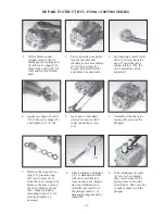
In order to drive the pump from the side opposite the present shaft extension, simply
remove the valve casing from the crankcase and rotate the pumps 180 degrees to the
desired position. Be certain to rotate the seal case (item #20) as well, so that the weep
holes are down at the six o'clock position. Exchange the oil fill and the oil drain plugs,
also. Refer to the repair instructions as necessary for the proper assembly sequence.
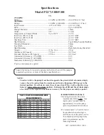
HORSEPOWER RATINGS:
The rating shown are the power
requirements for the pump. Gas
engine power outputs must be
approximately twice the pump
power requirements shown above.
We recommend a 1.15 service factor
be specified when selecting an
electric motor as the power source.
To compute specific pump horse
power requirements, use the
following formula:
HP = (GPM X PSI) / 1450
Consult the factory for special requirements that must be met if the pump is
to operate beyond one or more of the limits specified above.
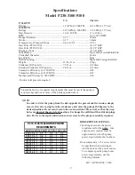
Specifications
Model P230-3100/5100
U.S.
(Metric)
1750 RPM
+
Ratings ............................................................ 1.1 GPM @ 2000 PSI ...... (4.2 LPM @ 137 bar)
3450 RPM
+
Ratings ............................................................ 2.05 GPM @ 2000 PSI .... (7.8 LPM @ 137 bar)
Inlet Pressure .................................................. 14 to 140 PSI .................... (1 to 10 bar)
RPM ........................................................................................................... Up to 3450 RPM
Plunger Diameter ............................................ 0.71” ................................. 18mm
Stroke .............................................................. 0.13” ................................. 3.4mm
Temperature of Pumped Fluids ...................... Up to 160
o
F ...................... (71
o
C)
Inlet Ports (P230-3100) ............................................................................. (2) 3/8” BSP
Inlet Ports (P230-5100) ............................................................................. (2) 1/2” BSP
Discharge Ports .......................................................................................... (2) 3/8" BSP
Shaft Rotation .............................................................................................. Top of Pulley Towards Fluid End
Crankshaft Diameter ................................................................................. 24mm
Key Width .................................................................................................. 8mm
Shaft Mounting .......................................................................................... Right Side Facing Manifold
Weight ............................................................. 11 lbs. 11oz. ..................... (5 kg)
Crankcase Oil Capacity .................................. 7.5 fl.oz. ........................... (0.2 liter)
Extended Crankcase Oil Capacity .................. 9.0 fl.oz. ........................... (0.3 liter)
Volumetric Efficiency @ 1750 RPM ........................................................ 0.94
Volumetric Efficiency @ 3450 RPM ........................................................ 0.87
Mechanical Efficiency @ 3450 RPM ....................................................... 0.86
+
Positive inlet pressure required
RPM GPM 1000 PSI 1500 PSI 2000 PSI
250
0.2
0.1
0.2
0.2
500
0.3
0.2
0.3
0.4
1000
0.6
0.4
0.7
0.9
1450
0.9
0.6
0.9
1.3
1750
1.1
0.8
1.1
1.5
3000
1.8
1.2
1.8
2.5
3200
1.9
1.3
2.0
2.6
3450
2.0
1.4
2.1
2.8
P230-3100/5100 HORSEPOWER
REQUIREMENTS

