07/12 MP4310_MP4135-3100.indd
GIANT INDUSTRIES, INC.
, 900 N. Westwood Ave., Toledo, Ohio 43607
PHONE (419) 531-4600, FAX (419) 531-6836, www.giantpumps.com
© Copyright 2012 Giant Industries, Inc.
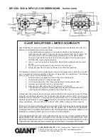
MP4130-3100 & MP4135-3100 DIMENSIONS - Inches (mm)
GIANT INDUSTRIES LIMITED WARRANTY
Giant Industries, Inc. pumps and accessories are warranted by the manufacturer to be free from
defects in workmanship and material as follows:
1. For portable pressure washers and car wash applications, the discharge mani
folds will never fail, period. If they ever fail, we will replace them free of charge. Our
other pump parts, used in portable pressure washers and in car wash applica
tions, are warranted for five years from the date of shipment for all pumps used in
NON-SALINE, clean water applications.
2. One (1) year from the date of shipment for all other Giant industrial and consumer
pumps.
3. Six (6) months from the date of shipment for all rebuilt pumps.
4. Ninety (90) days from the date of shipment for all Giant accessories.
This warranty is limited to repair or replacement of pumps and accessories of which the manufac-
turer’s evaluation shows were defective at the time of shipment by the manufacturer. The following
items are NOT covered or will void the warranty:
1. Defects caused by negligence or fault of the buyer or third party.
2. Normal wear and tear to standard wear parts.
3. Use of repair parts other than those manufactured or authorized by Giant.
4. Improper use of the product as a component part.
5. Changes or modifications made by the customer or third party.
6. The operation of pumps and or accessories exceeding the specifications set forth
in the Operations Manuals provided by Giant Industries, Inc.
Liability under this warranty is on all non-wear parts and limited to the replacement or repair of those
products returned freight prepaid to Giant Industries which are deemed to be defective due to work-
manship or failure of material. A Returned Goods Authorization (R.G.A.) number and completed
warranty evaluation form is required prior to the return to Giant Industries of all products under war-
ranty consideration. Call (419)-531-4600 or fax (419)-531-6836 to obtain an R.G.A. number.
Repair or replacement of defective products as provided is the sole and exclusive remedy provided
hereunder and the MANUFACTURER SHALL NOT BE LIABLE FOR FURTHER LOSS, DAMAGES,
OR EXPENSES, INCLUDING INCIDENTAL AND CONSEQUENTIAL DAMAGES DIRECTLY OR
INDIRECTLY ARISING FROM THE SALE OR USE OF THIS PRODUCT.
THE LIMITED WARRANTY SET FORTH HEREIN IS IN LIEU OF ALL OTHER WARRANTIES OR
REPRESENTATION, EXPRESS OR IMPLIED, INCLUDING WITHOUT LIMITATION ANY WAR-
RANTIES OR MERCHANTABILITY OR FITNESS FOR A PARTICULAR PURPOSE AND ALL SUCH
WARRANTIES ARE HEREBY DISCLAIMED AND EXCLUDED BY THE MANUFACTURER.


