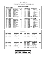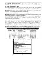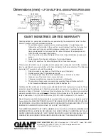
ITEM PART
DESCRIPTION
QTY
38
07140
O-Ring, Seal Case
3
38A
13241
Support Ring for 38
3
39
13012
O-Ring (LP600/LP600-4000)
3
39
12055
O-Ring (LP301A/LP301A-4000)
3
39A
13036
Support Ring for 39
(LP600/LP600-4000)
3
39A
07693
Support Ring for 39
(LP301A/LP301A-4000)
3
40
07322
V-Sleeve (LP600/LP600-4000)
3
40
06083
V-Sleeve (LP301A/LP301A-4000)
6
40A
07268
Pressure Ring (LP600)
3
40A
07268-0100 Pressure Ring, 316 S.S.
(LP600-4000)
3
40A
13366
Pressure Ring (LP301A)
3
40A
13366-0100 Pressure Ring, 316 S.S
(LP301A-4000)
3
40B
07270
Support Ring for 40 (LP600)
3
40B
07270-0100 Support Ring for 40, 316 S.S.
(LP600-4000)
3
40B
13367
Guide Ring for 40 (LP301A)
3
40B
13438
Guide Ring for 40, 316 S.S.
(LP301A-4000)
3
40C 05963
Sleeve (LP600/LP600-4000)
3
41
07338
Pressure Spring
(LP301A/LP301A-4000 Only)
3
43
13040
Valve Casing
1
44A
07150
O-Ring
9
44B
06266
Support Ring for O-Ring
3
45
06078
Compression Spring
3
46
08286
Valve Assy.,Complete
(LP600/LP600-4000)
6
46
07060
Valve Assy., Complete
(LP301A/LP301A-4000)
6
46A
07064
Valve Seat (LP301A/LP301A-4000)
6
46A
07064-0100 Valve Seat (LP600/LP600-4000)
6
46B
13130
Valve Plate (LP600/LP600-4000)
6
46B
07063
Valve Plate (LP301A/LP301A-4000)
6
46C 07062-0100 Valve Spring
6
46D 07066
Spacer Pipe
(LP301A/LP301A-4000)
6
46D 05472
Spacer Pipe (LP600/LP600-4000)
6
46E
05473
Valve Spring Guide
(LP600/LP600-4000)
6
48
06077
Plug
3
49
07157
Stud bolt
8
49A
07158
Hexagon Nut
8
49B
07159
Disc
8
50
12250
Plug, G-1/2”, S.S.
(LP301A/LP301A-4000 Only)
1
50A
06807
Steel Ring
1
52
13020
Disc for Crankshaft
1
53
06607
Hexagon Screw
1
54
13044*
Plug, G 1”
2
55
13151*
Plug, G 1-1/4”
2
ITEM PART
DESCRIPTION
QTY
1
07759
Crankcase
1
2
13000
Oil Filler Plug Assy.
1
3
05940
Cover Plate
1
3A
07223-0100 Spring Ring
2
3B
05051
Hexagon Screw
2
4
06085
Crankcase Cover
1
5
07104
O-ring, Crankcase Cover
1
6
05943
Oil Sight Glass w/Gasket
1
8
06086
Oil Dipstick Assy.
1
9
01009
O-Ring, (For Dipstick)
1
10
01010
Cylinder Screw (LP600/LP301A)
4
10
01010-0100 Cylinder Screw, 316 S.S.
(LP600-4000/LP301A-4000)
4
11
01011-0400
Spring Ring (LP600/LP301A)
5
11
01011-0100
Spring Ring, 316 S.S.
(LP600-4000/LP301A-4000)
5
12
07109
Plug, G1/2” (LP600/LP301A)
1
12
07109-0400 Plug, G1/2”, 316 S.S.
(LP600-4000/LP301A-4000)
1
13
07182
Gasket
1
14
07111
Bearing Cover
2
15
07112
Radial Shaft Seal
2
16
07113
O-Ring for Bearing Cover
2
17
07114
Hexagon Screw (LP600/LP301A)
8
17
07114-0100
Hexagon Screw, 316 S.S
(LP600-4000/LP301A-4000)
8
20
07116
Taper Roller Bearing
2
20A
07117
Fitting Disc
1-3
20B
13001
Fitting Disc
1-3
21
05376
Shaft Protector
1
21A
05377
Shaft Guard Holder
1
22
13242
Crankshaft
1
23
13243
Key
1
24
13340
Connecting Rod Assy.
3
24A
13277
Inner Hex Screw
6
24B
13278
Spring Washer
6
25
13341
Crosshead Assy.
3
28
13232
Crosshead Pin
3
29A
07125
Centering Sleeve
3
29B
07126
Plunger Pipe (LP600/LP600-4000)
3
29B
07127
Plunger Pipe
(LP301A/LP301A-4000)
3
29C 13031
Tensioning Screw
3
29D 07755
Copper Ring (LP600/LP301A)
3
29D 07161-0100 Crush Washer
(LP600-4000/LP301A-4000)
3
30
07779
Oil Scraper
3
31
07133
Oil Seal
3
35
13235
Seal Sleeve (LP600/LP600-4000)
3
35
13364
Seal Sleeve
(LP301A/LP301A-4000)
3
36
13237
Leakage Seal
(LP600/LP600-4000)
3
36
13238
Leakage Seal
(LP301A/LP301A-4000)
3
37
13239
Seal Case (LP600/LP600-4000)
3
37
13240
Seal Case (LP301A/LP301A-4000)
3
Parts List
LP301A/LP301A-4000/LP600/LP600-4000
*BSP to NPT Adapters/Seals (sold separately)
Inlet Port = 13377 (Adapter) / 13376 (Seal)
Discharge Port = 13373
+
(Adapter) / 13372 (Seal)
+
rated up to 3000 PSI. For higher pressure adapters, contact Giant.
5


