background image

2

INSTALLATION INSTRUCTIONS

Cooling the Gear Oil

Important! 

 The water input pressure must not 

exceed 2 bar when using the integrated system for 

cooling the gear oil (standard version). 

If a separate cooling circuit (maximum 29 PSI [2 

bar]) is installed, it is then possible to have an input 

pressure of up to maximum 145 PSI (10 bar) on the 

suction side.

Make sure that suction pulsation is sufficiently 

dampened - water column resonance must be 

avoided.

Important!

  The pumps can be run without gear 

oil cooling in continuous operation 

up to

 a power 

rating of 

107 hp (80 kW)

 or with major intermittent 

operation).

If operation power 

exceeds 107 hp (80 kW)

 or if 

continuous operation is the case, the pump must 

be run with the integrated oil cooling system.  The 

maximum temperature of the water being pumped 

and which is also fed through the cooling system 

must not exceed 86 °F (30°C).  The amount which 

is fed into the cooling system depends on the pump 

speed and is approximately 1.85 GPM (7.0 L/min) at 

580 RPM.  The cooling water is sucked in by one of 

the pumping chambers and pumped away.

The stated figures are for maximum pressure and 

maximum speed (RPM) and apply for interval 

operation with cold water.

Required NPSH refers to water (specific weight 1kg/

dm

3

, viscosity 1°E) at maximum permissible pump 

revolutions.

Fluid medium: Clean water filter with 50µm.

Operation and Maintenance

Check oil level prior to starting and ensure trouble-

free water supply.

Important!

  If there is a 

danger of frost

, the water 

in the pump and in the pump fittings (particularly 

the unloader valve) must be emptied. The second 

discharge port can also be used and the pump run 

“dry” for 1-2 minutes for this purpose.

Oil: Use only 3.3 Gallons (12.5 liters) of ISO VG 220 

GL4 (e.g. Aral Degol BG220) or SAE 90 GL4 gear oil 

(Giant p/n 01154).  Initial change after 50 operating 

hours and then every 1000 operating hours after one 

year at the latest.

Important! 

 When operating in damp places or with 

high temperature fluctuations, oil must be changed 

immediately should condensate (frothy oil) occur in 

the gear box.

NPSH values must be observed.

Summary of Contents for GP8055-Brine

Page 1: ...s List pages 6 7 Repair Kits Tool List page 8 Torque Specifications page 8 Troubleshooting Chart page 8 Repair Instructions pages 9 11 Dimensions back page Warranty Information back page Triplex Ceram...

Page 2: ...and is approximately 1 85 GPM 7 0 L min at 580 RPM The cooling water is sucked in by one of the pumping chambers and pumped away The stated figures are for maximum pressure and maximum speed RPM and a...

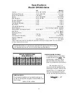
Page 3: ...cted in this case Specifications Model GP8055 Brine Consult the factory for special requirements that must be met if the pump is to operate beyond one or more of the limits specified above HORSEPOWER...

Page 4: ...ontacted in this case Specifications Model GP8060 Brine Consult the factory for special requirements that must be met if the pump is to operate beyond one or more of the limits specified above HORSEPO...

Page 5: ...contacted in this case Specifications Model GP8065 Brine Consult the factory for special requirements that must be met if the pump is to operate beyond one or more of the limits specified above HORSEP...

Page 6: ...6 Exploded View GP8055 GP8060 GP8065 Brine...

Page 7: ...ng 3 40 07723 Seal Ring GP8055 3 40 05067 Seal Ring GP8060 3 Item Part Description Qty 40 06996 Seal Ring GP8065 3 41 05276 Pressure Ring GP8055 3 41 05068 Pressure Ring GP8060 3 41 05117 Pressure Rin...

Page 8: ...g examine valve casing for unevenness on the sealing surfaces Oil leaks at visible part of plunger Gear sealing is leaky Examine seals and running surface of plunger Dirty mile colored frothy oil Oil...

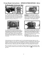
Page 9: ...t with silicon grease or molycote anti seize Cu 7439 when reassembling Be fore refitting the valves clean the sealing sur faces in the casing and check for any damage Tighten caps 58 at 133 Ft lbs che...

Page 10: ...other side of the seal sleeve 9 Coat the seal sleeve lightly with anti corrosive grease e g molycote no Cu 7439 in its fitted area towards the crankcase Insert the seal sleeves in to their crankcase f...

Page 11: ...of each crank pin Fit the bearing cover 14 and tighten the screws 17 at 64 Ft lbs Seal 32A must always be installed so that the seal lip on the inside diameter faces the oil Possible axial float of t...

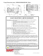
Page 12: ...tries Inc Liability under this warranty is on all non wear parts and limited to the replacement or repair of those products returned freight prepaid to Giant Industries which are deemed to be defectiv...

Reviews: