GHM Group
– Martens
GHM Messtechnik GmbH | Kiebitzhörn 18 | 22885 Barsbüttel | Germany
Phone +49-40-670 73-0 |
| www.ghm-group.de
10
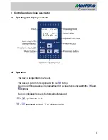
The device initialises after the supply voltage is connected. The device type and
software version appear in the display. After the device is finished initialising, it en-
ters the operating level and the current temperature and all safety-related settings
are displayed. The peak value buffer is displayed by briefly pressing the
button.
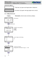
The configuration level is displayed by pressing and holding the
button for 2
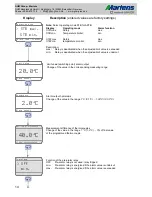
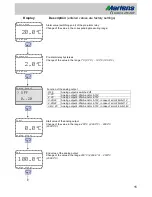
seconds. All parameters determining the properties of the device are programmed
here. A password must be entered in order to enter the safety area of the configu-
ration level. If an incorrect password is entered, an error message appears in the
display. The device switches back to the operating level after this message or if no
password is entered. After an incorrect password has been entered three times, the
device enters a safety timeout for 60 minutes. The progress of this safety timeout is
shown in the display. The safety area is accessible with entry of the correct pass-
word. Settings can be made here, which must be protected from unauthorised
change. After the last menu item or if no button is pressed for more than 2 minutes,
the devices switches back to operating level automatically and the current meas-
urement is shown in the display. The configuration level can be exited at any times
by pressing the
button for 2 seconds.
Error messages
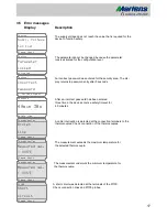
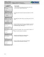
If errors occur, the messages are shown in clear text on the display. This
simplifies troubleshooting.
Note for commissioning!
The device has standard preconfigured factory settings. Therefore, it
must be adapted to the specific application.
Service
Service of the device is only possible in the factory. Please refer to
chapter 6 Return to manufacturer on page 24.
Requirements
- It is necassary to keep the conditions of the ATEX EC-Type Examina-
tion Certificate.
- The device must be installed in dry and good monitored rooms.
- If the intrinsinc safety input is connected to the dust andangered area of
zone 20 or 21, it has to be ensured
hat the corresponding devices in this circuit have the requirements of catagory
1D or 2D.
- Reparing and design modifications are only allowed at works.
Summary of Contents for STL50Ex
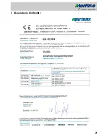
Page 25: ...25 9 Declaration of Conformity ...
Page 27: ...27 ...

