12
2.
Base Frame installation
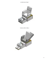
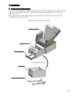
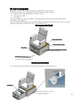
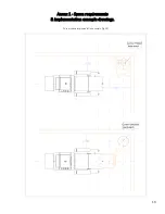
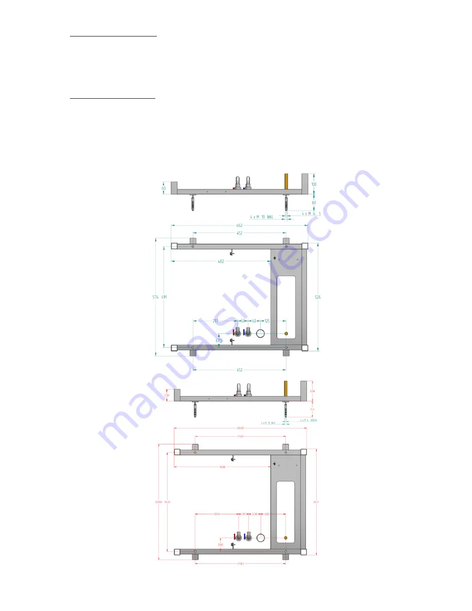
The first and lonely part to fix to the ground is “the Base frame” (fig.9), please make sure to identify the four
fixation holes
(refer to the below drawing fig. N°10)
and be aware of the space requirements and related
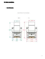
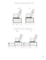
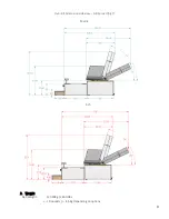
full spread dimensions you can find see in overall dimensions.
Refer to the (drawing fig. N°7).
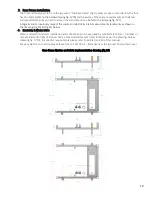
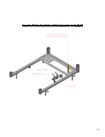
Integrally and scrupulously respect the water and electricity inlets measurements landmarks as shown in
the drawing (fig.10) & (fig.11) below.
3.
Electricity & Water Inlets
Water and electricity inlets Installation and connections to be executed by certified electrician / plumber in
respect and conformity of all local norms. Please identify exact inlets locations as per the drawings below
(drawing fig. N°10). For specific requirements please refer to points 9 and 10 of this manual.
For easy electric connection please leave free coil of 100cm – 40inches over the ground final surface level.
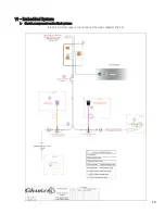
Base frame fixation and inlets implementation drawing (fig.10)
Summary of Contents for Pedispa Compact
Page 6: ...6 Unfolded position fig 2 Full Spread Position fig 3...
Page 7: ...7 III Before Installation 1 Over All Dimension Over All Dimension front view fig 4 Metric Inch...
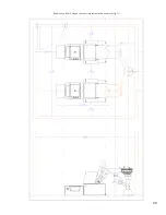
Page 13: ...13 Perspective of the Base frame fixation and inlets implementation drawing fig 11...
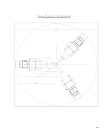
Page 20: ...20 Room space dual Pedispa compact Implementation example fig 17...
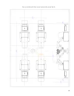
Page 21: ...21 Room space Quadruple Pedispa compact Implementation example fig 18...

