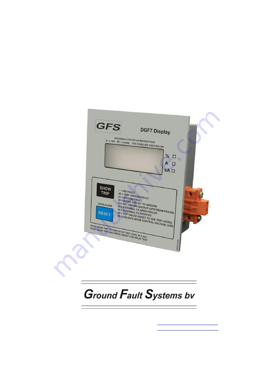
DGF7 Display
reference manual
Ground Fault Systems B.V. Rigtersbleek-Aalten 4B15
7521 RB Enschede The Netherlands
www.groundfaultsystems.com
[email protected]
Tel: +31 53 4318628 CofC: 55400914
Page 1: ...DGF7 Display reference manual Ground Fault Systems B V Rigtersbleek Aalten 4B15 7521 RB Enschede The Netherlands www groundfaultsystems com info groundfaultsystems com Tel 31 53 4318628 CofC 55400914...
Page 2: ...2 Datalink error code 6 3 PARAMETER SETTING 7 3 1 Display Settings 7 3 2 Display setup procedure 7 4 CONNECTIONS AND PRECAUTIONS 8 5 TECHNICAL SPECIFICATIONS 9 5 1 Serial datalink circuit 9 5 2 Termi...
Page 3: ...arameters inside the display itself that modify its behaviour The DGF7 Display has settable parameters to enable the user to tailor the DGF7 Display to their needs Relay Test on off G F Current Displa...
Page 4: ...xceeds the system s measuring range the display shows Out meaning Out of range Depending on various internal variables the maximum value that can be represented whether in relative or absolute format...
Page 5: ...ful when pulse tripping a breaker that also supplies control voltage to the G F protection system Especially when several systems control one single breaker with their relay contacts in parallel which...
Page 6: ...is already tripped the display will show a 1 5 seconds message See chapter 3 for the parameter settings 2 1 7 LCD test The LCD panel can be tested at all times by keeping the RESET button pressed long...
Page 7: ...p Level that is set on the DGF7 3 dipswitches please check the box on the front panel 1 1 Absolute mode G F Current is displayed in A or kA as is applicable If a 5000 5 interposing CT is used check th...
Page 8: ...rt terminals Terminals will accept 0 5 2 5 mm2 20 14 AWG solid or stranded conductors The user may want to identify the following terminals as indicated on the display s product label S1 for connectin...
Page 9: ...ollution degree 3 over voltage category III Insulation stripping length 7 mm Torque 0 4 0 6 Nm Field wiring 0 5 2 5 mm2 VDE 20 14 AWG UL CSA Cu solid or stranded 5 3 Environment Operating temperature...
Page 10: ...4 3 Radiated electromagnetic field immunity EN 61000 4 4 Electromagnetic compatibility EMC for industrial process measurement and control equipment Part 4 4 Electrical fast transient burst immunity EN...
Page 11: ...L R R R L R R R 0 030 A 0 100 A 0 250 A 0 37 A 0 50 A 1 00 A 3 00 A 0 060 A 4 5 6 Ground Fault Trip Delay time and Trip Inhibit L L L L L R L R L L R R R L L R L R R R L R R R 20 ms without Trip Inhi...
Page 12: ...A 0 37 A 0 37 kA 0 74 A 1 48 A 7 4 A 37 A 0 50 A 0 50 A 0 50 kA 1 00 A 2 00 A 10 0 A 50 A 1 00 A 1 00 A 1 00 kA 2 00 A 4 0 A 20 0 A 100 A 3 00 A 3 00 A 3 00 kA 6 0 A 12 0 A 60 A 300 A 0 060 A 0 060 A...
Page 13: ...ream device failed to trip The DGF7 3 then tripped as a last resort The contactor should be inspected since its contacts may well be damaged 04 EXTERNAL CS OPEN CIRCUIT The connection to an external C...
Page 14: ...PAGE 14 OF 15 DGF7 Display reference manual rev 1 feb 22 2022 Ground Fault Systems B V 7 4 Figure 1 Typical Field Connection using DGF7 3 with built in core balance remote reset and DGF7 Display...
Page 15: ...PAGE 15 OF 15 DGF7 Display reference manual rev 1 feb 22 2022 Ground Fault Systems B V 7 5 Figure 2 Dimensions DGF7 Display...