page 3 of 8
8350-3 Temperature Transmitter Instructions
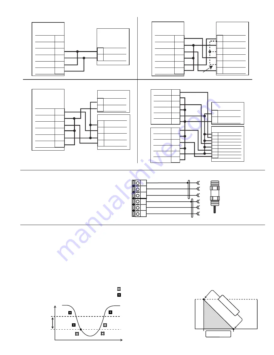
3.1 System Power/Loop Connections
3.2
Sensor Input Connections
Wiring Tip:
Do not route sensor cable in any conduit
containing AC power wiring - electrical
noise may interfere with the signal.
•
Off:
Disables output pulse.
•
Proportional Pulse Mode Operation
The output emits a 100 mS pulse (simulated contact closure) at
rate defined by the Output, Pulse Range, Output Rate, and the
process condition (0 to 400 pulses/minute, as programmed)
Example: As the process falls below 10 the output will start
pulsing in relation to the process value, the max pulse endpoint
and the programmed pulses/min. Pulse rate will increase as
the process approaches the programmed endpoint.
3.3 Open Collector Functions
•
Low:
Output triggers when process variable is less than
setpoint.
•
High:
Output triggers when process variable is higher than
setpoint.
Example: In Low Alarm Mode Operation, the output becomes
active when the process drops below the setpoint, and
becomes inactive when the process rises above the setpoint
plus hysteresis. The opposite is true for High Alarm Mode.
Stand-alone application, no current loop used
Transmitter
Terminals
6
5
4
3
2
1
Loop2-
Loop2+
Sys. Pwr.
Loop -
Sys. Pwr.
Loop +
AUX
Power -
AUX
Power +
Power Supply
DC 12 - 24 V
Power
Supply
Power
Supply
-¤
+
Connection to a PLC with built-in power supply
PLC
Terminals
Power Supply
Ground
Power
Supply
Channel 2
4-20 mA in
Channel 2
4-20 mA in
Channel 1
4-20 mA in
Channel 1
4-20 mA in
-¤
+¤
-¤
+¤
-¤
+
Internal PLC
Connection
NC
NC
Connection to a PLC/Recorder, separate supply
PLC or Recorder
Channel 2
4-20 mA in
Channel 2
4-20 mA in
Channel 1
4-20 mA in
Channel 1
4-20 mA in
-¤
+¤
-¤
+
DC 12 - 24 V
Power
Supply
Power
Supply
-¤
+
PLC or Recorder
- Channel 4
+ Channel 4
- Channel 3
+ Channel 3
- Channel 2
+ Channel 2
- Channel 1
+ Channel 1
DC 12 - 24 V
Power
Supply
Power
Supply
-¤
+
Transmitter
Terminals
6
5
4
3
2
1
Loop2-
Loop2+
Sys. Pwr.
Loop -
Sys. Pwr.
Loop +
AUX
Power -
AUX
Power +
Transmitter
Terminals
6
5
4
3
2
1
Loop2-
Loop2+
Sys. Pwr.
Loop -
Sys. Pwr.
Loop +
AUX
Power -
AUX
Power +
6
5
4
3
2
1
Loop2-
Loop2+
Sys. Pwr.
Loop -
Sys. Pwr.
Loop +
AUX
Power -
AUX
Power +
6
5
4
3
2
1
Loop2-
Loop2+
Sys. Pwr.
Loop -
Sys. Pwr.
Loop +
AUX
Power -
AUX
Power +
T
ransmitter 1
T
ransmitter 2
Example: Two transmitters connected to PLC/Recorder
with separate power supply
Silver (Snsr 2 Gnd)
Red (Snsr 2 IN)
Black (Snsr 2 V+)
Silver (Snsr 1 Gnd)
Red (Snsr 1 IN)
Black (Snsr 1 V+)
16
15
14
13
12
11
+GF+ SIGNET 2350
Temperature Sensors
Terminals
Hysteresis
Output active
Output inactive
Time
Setpoint
Process
Relay 1
or Relay 2
10
5
Relay 1: Pulse
10.0000
→
5.0000>
Output1 Rate:
100 Pulses/min>
I 10I =I
1I pulses/min.
I7.5I =I 50I pulses/min.
I 5I =I 100I pulses/min.
Start
→
max. pulse endpoint
Pulse rate
Process variable
0 pulses
100 pulses


