background image

PV System

installers guide

Models: 2200W AC/950W DC; 1500W AC/950 DC

Before operating and installation, carefully read all instructions. Do not discard this manual.

Summary of Contents for 1500W AC/950 DC

Page 1: ...PVSystem installersguide Models 2200WAC 950WDC 1500WAC 950DC Beforeoperatingandinstallation carefullyreadallinstructions Donotdiscardthismanual...

Page 2: ...nels 8 Mounting of PV Panels 8 Installation of the pv panels 9 General 9 Installation 9 Installation of the element 12 Screw in elements 12 Flange Type Elements 13 Installation of the Geyserwise Dual...

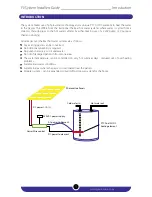
Page 3: ...nverted No Additional plumbing is required No pumps necessary to circulate water No risk of damaged panels in frost prone areas The water temperature can be controlled on very hot summer days reduced...

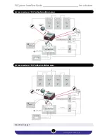
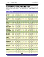
Page 4: ...N2 PV Bat Pump Ground System overview 100L for high irradiation areas System overview 100L for low irradiation areas See table on page 5 PV System Installers Guide _________________________ Introduct...

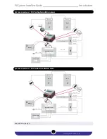
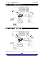
Page 5: ...ump Ground Battery 3 LDR outside Set voltage on MPPT 300W PV panel 300W PV panel 300W PV panel 1 1 2 1 CN5C RT GeyserWise control Thermostat PTC element White DC Blue DC Black AC Red AC 4 4 0 1 Isolat...

Page 6: ...ound Battery 3 LDR outside Set voltage on MPPT 250W PV panel 250W PV panel 250W PV panel 250W PV panel 1 1 1 2 1 CN5C RT Thermostat PTC element White DC Blue DC Black AC Red AC 4 4 0 1 Isolator switch...

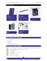
Page 7: ...6 66 6 08 5 41 4 76 4 16 3 78 4 03 4 73 5 60 5 94 6 20 6 53 EMBALENHLE 6 39 5 83 5 19 4 54 3 99 3 66 3 88 4 57 5 43 5 63 6 03 6 28 JOHANNESBURG 6 70 6 10 5 46 4 77 4 21 3 80 4 08 4 78 5 69 5 98 6 29 6...

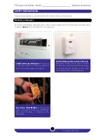
Page 8: ...miliarity with all local safety procedures Step 3 Mount the PV Panels Step 4 Install element Step 5 Install Geyserwise Dual Controller Step 6 Install MPPT Step 7 Recheck all connections Step 9 Switch...

Page 9: ...to ensure that there is no current on the wires IMPORTANT Make sure that there is no reading on the multimeter Switch off the circuit breaker of the geyser at the main DB This is done to ensure that...

Page 10: ...der to secure an electrical connection Do not touch or handle PV modules with broken glass separated frames or a damaged backsheet unless the PV modules are first disconnected and you are wearing prop...

Page 11: ...the instructions to fix the PV module to the bracket Installation and maintenance shall be performed in accordance to all electrical safety regulations Do not stand on the modules Do not paint the mod...

Page 12: ...n the location and choose what is here A green arrow will then appear if you click on that arrow you will get the GPS coordinates for that spot on the map The first numbers is the latitude of the spot...

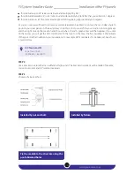
Page 13: ...m2 to 6mm2 is recommended and ground clamp is recommended See picture STEP 5 Wiring and connection Use 4mm or 6mm cable depending on distance of panels from the MPPT 4mm for up to 20m For longer dista...

Page 14: ...y steps on page 6 2 Shut OFF cold water supply to the geyser open the hot water faucet attach a hose to the drain valve open the drain valve on the GEYSER and drain the water 3 Remove access cover and...

Page 15: ...er before attempting to remove the wires 12 Inspect wiring If corrosion is present on wiring cut and strip wire 1 2 only if wire is long enough If corrosion is still present or wire is not long enough...

Page 16: ...trip wire 1 2 Only if wire is long enough If corrosion is still present or wire is not long enough consult electrician for wire replacement and wire gauge selection Loose corroded or faulty wiring con...

Page 17: ...thegeyser Switch off isolator switch in the roof The isolator switch acts as a switch to isolate both live and neutral from the main supply should someone accidentally switch on the main supply or the...

Page 18: ...bles for extensions Remove the existing thermostat by disconnecting all the wires on the connector terminal block of the thermostat Replace the conventional element with the GeyserWise AC DC element a...

Page 19: ...or the negative of the MPPT in case a MPPT controller is used The blue wire is connected to the negative of the load side of the solid state relay in case a MPPT controller is used or the negative of...

Page 20: ...ight outside STEP 5 Install the LDR sensor You will be supplied with an extension cable Do not use any other extension than the extension cable provided Plug the LDR sensor into the control box at the...

Page 21: ...itch The Red wire is your Live wire The Black wire is your Neutral The other wire provided is your Earth Each control box has knock outs at the bottom of the unit To make an entry into the control box...

Page 22: ...h the requirements of SANS 10142 Connect Live and Neutral as indicated Ensure that the wires are properly fastened as they are drawing a large current Loose connections can damage the connector block...

Page 23: ...Connect wires to geyser s connector block Fasten all connections with the cord grip and screws as indicated to ensure that the wire cannot be moved 3 4 Ensure the geyser is earthed as indicated in ca...

Page 24: ...on power at isolator switch MPPT CONNECTION MPPT Positive Plug MPPT connector cable into the MPPT MPPT Negative 1 3 2 www geyserwise co za Replace lid on control box and fasten properly Before you rep...

Page 25: ...y Day of the week Real time clock Element on off indicator Timers DC Indicater Display Error messages DISPLAY The display is the feedback mechanism to the user and displays important information about...

Page 26: ...ek flashes 1 Adjust the day of the week by using the and v arrow buttons 2 Adjusting the real time clock To adjust the real time clock follow the steps below Press the green set button until the time...

Page 27: ...y and not to the set times that the elements must come on Set the temperature per block to user requirements by using and v arrow keys To adjust the maximum temperature settings press the green set bu...

Page 28: ...u can set different timers for the weekend Setting DC differential setting Set the DC differential between 3 7 C by using the up and down arrow keys 2 Press the green set button until three digits dis...

Page 29: ...dicators and Saturday and Sunday flashes Press the green set button until the timer indicators and Monday to Friday flashes The below picture shows that you are at the Monday to Friday setting for tim...

Page 30: ...6 C at which time the element switches back again For example Let s say the hour indicator indicates 30 hours You then multiply the number of hours with your geyser element rating e g 4 kW This then...

Page 31: ...e information on page 21 Errorcode E3 Sensorfailurewatergeyser Possiblecause The sensor could be damaged or there is a connection problem Action s Replace sensor Check electrical connections and or pl...

Page 32: ...ve from this the voltage and current outputs required for maximum power to be achieved It will then calculate the load that it must simulate based on these voltage and current levels R V I The regulat...

Page 33: ...mme Geyserwise MPPT Controller Ensure that 4mm Solar Cable is used Use Cables as Supplied Battery 3 LDR outside Set voltage on MPPT 250W PV panel 250W PV panel 1 2 1 CN5C RT GeyserWise control Thermos...

Page 34: ...ement PV MPPT setting 100L Set at 65V 2 x 250W panels in series 150L Set at 100V 3 x 250W panels in series 200L Set at 110V 3 x 300W panels in series Adjust the pod until the heating light comes on Al...

Page 35: ...www geyserwise co za 33 PV System Installers Guide ___________________________________ NOTES...

Page 36: ...eBagX103 Suite239 N1City 7463 physicaladdress151CookStreet Goodwood 7460 WesternCape tel 086 104 3973 fax 086 664 3973 PRETORIA physical address Unit 5 Edison Park 183 Edison Crescent Hennops Park Cen...

Reviews: