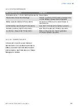
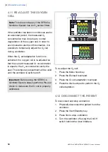
background image

4.7 SET ALARM LIMITS

S

V

S

-5087_XX

To set alarm limits:

1.

Press the Alarm Profile fixed key.

2.

Press the touchpad corresponding to the

alarm limit you want to adjust or press the

Alarm sound level touchpad.

3.

Turn the Main Rotary Dial to adjust values.

4.

Confirm each setting by pressing the

parameter touchpad or Main Rotary Dial.

5.

Press Autoset, if desired, to get a proposal

for alarm limits in VC, PC, and PRVC

modes.

Important:  Before accepting Autoset

values, make sure they are appropriate

for the patient. If not, enter settings

manually.

6.

Press Accept to activate the new alarm

limits.

Important:  Before accepting Autoset

values, make sure they are appropriate for

the patient. If not, enter settings manually.

Notes:

Autoset is not possible in Standby

because the ventilator requires patient

values in order to propose alarm limits.

Autoset is not available in supported or

NIV (optional) modes.

Current alarm limits are displayed during

ventilation in smaller figures to the right

of the parameter display.

The Main Rotary Dial becomes

inoperative for 2 seconds when a defined

safety limit for the alarm limit being

adjusted is reached. After this, it will be

operable again.

SERVO-s VENTILATOR SYSTEM V7.0, User's Manual

53

Operation overview

 | 4 |

Summary of Contents for Maquet SERVO-s VENTILATOR SYSTEM V7.0

Page 1: ...x User s Manual SERVO s VENTILATOR SYSTEM V7 0 ...

Page 2: ......

Page 3: ... 5 67 Ventilation modes and functions 6 119 Alarms 7 127 Optional Accessories 8 131 System messages 9 139 Start up configuration 10 143 Technical data 11 163 Definitions 12 165 Appendix User interface 13 177 Certificates 14 179 Index 15 SERVO s VENTILATOR SYSTEM V7 0 User s Manual Infologic 1 64 2 1 3 TABLE OF CONTENTS ...

Page 4: ...4 SERVO s VENTILATOR SYSTEM V7 0 User s Manual Infologic 1 64 2 1 TABLE OF CONTENTS ...

Page 5: ...1 INTRODUCTION TABLE OF CONTENTS 6 Device description 1 1 8 Warning Caution Important and Note 1 2 13 Version and Configurations 1 3 SERVO s VENTILATOR SYSTEM V7 0 User s Manual 5 Introduction 1 ...

Page 6: ...treating and monitoring patients ranging from pediatrics to adults with respiratory failure or respiratory insufficiency 1 1 4 INTENDED USER The SERVO s Ventilator System should be used only by those who are professional healthcare providers and have received training in the use of this system and have experience of ventilation treatment 1 1 5 INTENDED USE ENVIRONMENT The SERVO s Ventilator System...

Page 7: ... recommend that all service on the SERVO s Ventilator System should be performed as part of a service contract with MAQUET 1 1 8 DISCLAIMERS Improper Use Environment MAQUET has no responsibility for the safe operation of SERVO s Ventilator System if the Intended Use Environment requirements specified in this document are not followed Nonprofessional Servicing MAQUET has no responsibility for the s...

Page 8: ...erform a Pre use check before connecting the ventilator to a patient If any of the following occurs discontinue use of the ventilator and contact a service technician Unfamiliar pop up windows on the screen Unresolvable alarms Unfamiliar sounds Any unfamiliar or unexplained event Keep the ventilator upright during use Make sure that ventilation is started when a patient is connected to the ventila...

Page 9: ...entilation or circulatory impairment The SERVO s Ventilator System is not intended to be used during radiotherapy since this may cause system malfunction The SERVO s Ventilator System must not be used in a hyperbaric chamber The SERVO s Ventilator System must not be used with helium Only accessories supplies and auxiliary equipment recommended by MAQUET should be used with the ventilator system Us...

Page 10: ...rm to relieve the patient from the weight of the tubing system is recommended When using the MCare Remote Service function install the network cable so that there is no risk of anyone tripping over it Do not leave the patient unattended when connected to the ventilator MAQUET has no responsibility for the safe operation of SERVO s Ventilator System if the Intended Use requirements specified in thi...

Page 11: ...system Avoid contact with external electrical connector pins 1 2 3 FIRE HAZARD WARNINGS Keep the system and its gas hoses clear of all ignition sources Do not use the system with worn or frayed hoses or hoses that have been contaminated by combustible materials such as grease or oil Oxygen enriched gas is extremely flammable if you detect a burning odor disconnect the oxygen supply mains power and...

Page 12: ...whole system If a scavenging system i e gas evacuation is connected to the ventilator it must conform to ISO8835 3 guidelines for subatmospheric pressure and induced flow Measurements of parameter values that have been processed by auxiliary equipment may be inaccurate if equipment not authorized by MAQUET is used should be discounted if they conflict with information on the ventilator screen must...

Page 13: ...0 250 kg 1 3 2 CONFIGURATIONS The SERVO s Ventilator System can be used in both invasive and non invasive ventilation Standard Configuration Options Bi Vent Non Invasive Ventilation NIV Lung Mechanics PRVC incl SIMV PRVC PS PC incl SIMV PC PS VC incl SIMV VC PS PS CPAP SERVO s VENTILATOR SYSTEM V7 0 User s Manual 13 Introduction 1 ...

Page 14: ...14 SERVO s VENTILATOR SYSTEM V7 0 User s Manual 1 Introduction ...

Page 15: ...lator 2 1 18 User Interface Connections labels and symbols 2 2 21 Navigating the User Interface 2 3 28 Patient Unit Connections labels and symbols 2 4 34 Transport and storage 2 5 SERVO s VENTILATOR SYSTEM V7 0 User s Manual 15 System Overview 2 ...

Page 16: ...r calculated value results in the adjustment of gas delivery to achieve the target value The system has two gas modules one for air and one for O2 Gases may be supplied by a medical pipeline system a compressor or by gas tanks Ensure that the ventilator is in its locked position on the cart or holder used to prevent unintentional movements CAUTION Lock the wheels if the ventilator is not to be use...

Page 17: ...SYSTEM COMPONENTS 1 Air and O2 supply 2 Power cable 3 User Interface 4 Patient Unit 5 Expiratory inlet 6 Servo Duo Guard viral bacterial filter 7 Inspiratory outlet 8 Patient circuit 9 Emergency air intake SERVO s VENTILATOR SYSTEM V7 0 User s Manual 17 System Overview 2 ...

Page 18: ...ser Interface includes a screen with active touchpads fixed keys a rotary dial 2 2 1 USER INTERFACE DIAGRAM SVS 0013_XX 24 21 18 19 20 22 23 6 7 8 9 10 1 2 3 12 14 15 13 4 5 11 17 25 26 27 16 18 SERVO s VENTILATOR SYSTEM V7 0 User s Manual 2 System Overview ...

Page 19: ...hing message Patient not ventilated is displayed on the screen directly above the word Standby 10 Start Standby key 11 Luminescence detector for automatically adjusting screen brightness 12 Text messages including patient triggering symbols 13 Alarm messages 14 Waveform area for monitoring two to three individually scaled parameters including a volume pressure loop and a flow volume loop 15 Measur...

Page 20: ...er Start ventilation Standby yellow indicates Standby Power indicator green indicates AC power connected Battery indicates ventilator is using battery power with estimated minutes remaining 12 V indicates that external 12V DC is connected 12 V ON OFF switch Trigger indication appears in the message alarm field when the patient triggers a breath Volume Control with flow adaptation Volume Control wi...

Page 21: ...uchpad is now highlighted in white with a blue frame and it is possible to set a new value 3 Turn the Main Rotary Dial to the desired value or line 4 Confirm each setting by pressing the parameter touchpad or pressing the Main Rotary Dial 5 The touchpad turns grey again indicating that the new setting has been entered 6 Press Accept to activate the new settings or Cancel to start over Important Di...

Page 22: ...that a new value can be entered 3 Turn the Main Rotary Dial to the desired value or line 4 Confirm the setting by pressing the Main Rotary Dial The parameter touchpad turns grey again indicating that a new setting has been entered 5 Touch Accept to activate your settings or Cancel to start over Note When the defined safety limits for a given parameter have been reached the Main Rotary Dial becomes...

Page 23: ...n group 1 activate user interface functions such as Save and access various screens such as Menu 2 The keys in group 2 start special ventilatory functions Important The special ventilatory functions require continuous supervision SERVO s VENTILATOR SYSTEM V7 0 User s Manual 23 System Overview 2 ...

Page 24: ...ct Access Knob corresponding to the parameter you wish to change until the desired value is displayed on the screen WARNING When you adjust a breathing parameter using a Direct Access Knob the parameter will change immediately starting with the next breath no additional confirmation is required The Main Rotary Dial and Direct Access Knobs become inoperative for 2 seconds when the user reaches a de...

Page 25: ...ng the corresponding parameter value is outside safety limits a text message is displayed accompanied by an audible signal 3 A red bar indicating the corresponding parameter value is significantly outside safety limits a text message is displayed accompanied by an audible signal Note When the defined safety limits for a given parameter have been reached the Direct Access Knob becomes inoperative f...

Page 26: ...shows a sheet icon press the touchpad to open a user interface window OR 3 If the touchpad shows an arrow icon press the touchpad to display the submenu Press any of the following touchpads 4 Alarm 5 Review 6 Compensate 7 Biomed 8 Panel lock For more information see Appendix User interface on page 165 26 SERVO s VENTILATOR SYSTEM V7 0 User s Manual 2 System Overview ...

Page 27: ...or is running on battery power the estimated remaining battery time in minutes is shown To access the status window 1 Press the Status touchpad Touchpads leading to status windows appear Press any of the following touchpads 2 General 3 O2 cell O2 Sensor 4 Expiratory cassette 5 Batteries 6 Pre use check 7 Patient Circuit SERVO s VENTILATOR SYSTEM V7 0 User s Manual 27 System Overview 2 ...

Page 28: ...e patient unit consists of the following components gas supplies and their connectors power supplies and their connectors connectors for accessories PATIENT UNIT DIAGRAM SVS 0048_XX 12V 28 SERVO s VENTILATOR SYSTEM V7 0 User s Manual 2 System Overview ...

Page 29: ...5 Manufacturing information 6 UDI label 7 Gas inlet for O2 8 Cooling fan with filter 9 Label 10 Label 11 Equipotentiality terminal 12 AC power supply connector with fuse 13 User interface connector 14 Fuse for external DC power supply 15 External 12V DC inlet 16 Alarm output connection 17 RS 232 connector 18 Inspiratory outlet 19 Expiratory inlet SERVO s VENTILATOR SYSTEM V7 0 User s Manual 29 Sys...

Page 30: ...ay be different depending on Patient Unit version User Interface connector Note This symbol may be different depending on Patient Unit version 10A Fuse for external DC power supply External 12V DC input Note This symbol may be different depending on Patient Unit version 12V Expiratory label gas flow from patient Explanation Symbol Inspiratory label gas flow to patient Gas exhaust port label exhaus...

Page 31: ...PATIENT UNIT GAS FLOW DIAGRAM 1 2 3 4 5 6 7 8 9 10 11 12 from Patient to Patient SVS 0099_EN SERVO s VENTILATOR SYSTEM V7 0 User s Manual 31 System Overview 2 ...

Page 32: ...inspiratory channel also contains a safety valve 8 The patient breathing systems expiratory tubing is connected to the expiratory inlet The inlet also contains a moisture trap 9 The gas flow through the expiratory channel is measured by ultrasonic transducers 10 The expiratory pressure is measured by the expiratory pressure transducer located inside the ventilator The transducer is protected by a ...

Page 33: ...e if packaging is damaged Attention consult documentation Manufacturer CE label indicates compliance with the requirements of the Medical Device Directive 93 42 EEC Manufacturing date Federal law restricts this device to sale by or on the order of a physician Rx ONLY Humidity limitation Temperature limitation 55o C 10o C Type B indicates classification according to IEC 60601 1 EN 60601 1 Fragile h...

Page 34: ...connected follow facility guidelines and Use the handles on the Mobile Cart Transport the bed and the ventilator slowly and watch the patient connection carefully to see that no pulling or other movement occurs When moving the Support Arm or changing position watch the patient connection carefully to see that no pulling or other movement occurs Be careful not to tip the Mobile Cart when crossing a...

Page 35: ...3 POWER SUPPLY TABLE OF CONTENTS 36 Introduction 3 1 36 Viewing battery status 3 2 38 Alarms and safety 3 3 SERVO s VENTILATOR SYSTEM V7 0 User s Manual 35 Power supply 3 ...

Page 36: ...cted battery modules are being recharged This does not affect ventilation Alarms and Messages See Alarms and Safety on page 38 When the ventilator is turned off with the on off switch batteries continue to charge 3 2 VIEWING BATTERY STATUS When operating from batteries the estimated remaining battery time in minutes is displayed in the upper right corner of the screen on the Status touchpad WARNIN...

Page 37: ...charge 2 boxes filled 26 50 relative charge 3 boxes filled 51 75 relative charge 4 boxes filled 76 100 relative charge Remaining operating time in minutes Activity Instruction an instruction may be displayed next to the remaining operating time in minutes Response Activity Instruction Order a new battery module Expires soon The battery is no longer reliable replace it immediately Replace battery S...

Page 38: ...backup two fully charged battery modules must be installed at all times Always replace batteries when the ventilator software notifies you of imminent expiration or of diminished operating capacity Dispose of batteries according to local regulations and not with ordinary waste After a new battery module is installed display the Battery Status Window to ensure safe battery operation When delivered ...

Page 39: ...an 10 minutes left of battery operation Limited battery capacity High Priority Alarm Less than 3 minutes left of battery operation No battery capacity High Priority Alarm Battery voltage too low Cannot guarantee continued ventilator operation Low battery voltage High Priority Alarm 3 3 3 AC POWER FAILURE In the event of an AC power failure or disconnection the ventilator switches to battery operat...

Page 40: ...40 SERVO s VENTILATOR SYSTEM V7 0 User s Manual 3 Power supply ...

Page 41: ...patient data 4 4 51 Select the Type of Ventilation Options 4 5 52 Set ventilation mode 4 6 53 Set alarm limits 4 7 54 Start ventilation 4 8 55 Additional settings window 4 9 56 Suctioning 4 10 58 Re adjust the Oxygen cell 4 11 58 Disconnect the patient 4 12 SERVO s VENTILATOR SYSTEM V7 0 User s Manual 41 Operation overview 4 ...

Page 42: ... Pre use check includes tests and measurements of internal technical functionality gas supply internal leakage pressure transducers safety valve O2 cell O2 sensor flow transducers battery modules patient circuit leakage patient circuit compliance patient circuit resistance WARNINGS Always perform a Pre use check before connecting the ventilator to a patient The volume of the patient circuit used d...

Page 43: ...ble sources of alarm signals have been verified and the alarm system operates correctly 4 2 1 START UP 1 Connect power and gas supplies Power AC outlet Gas Air and O2 CAUTION Ensure that the cable to the User Interface is never disconnected while the SERVO s Ventilator System is powered on 2 Turn the ventilator on SERVO s VENTILATOR SYSTEM V7 0 User s Manual 43 Operation overview 4 ...

Page 44: ...ratory inlet Important Use only the MAQUET test tube 4 2 3 BATTERY SWITCH TEST The Pre use check tests the ventilator s ability to switch between AC and battery power when AC power is lost and restored When the on screen instruction appears disconnect the ventilator from AC power When the on screen instruction appears reconnect the ventilator to AC power Note This test will not be performed if the...

Page 45: ...t be filled with water SVX 155a_XX Important When blocking the end of the complete breathing system make sure there is no leakage Leakage will affect the circuit compliance compensation calculation 2 Block the end of the complete breathing system and follow the on screen instructions The circuit compliance and resistance are automatically measured Go to Compensate for Circuit compliance see page 4...

Page 46: ... a Patient Circuit Test must be performed Note Circuit compliance compensation is not available in NIV modes option 4 2 6 TEST ALARM OUTPUT CONNECTION OPTION If the Alarm Output Connection option is installed a dialog for the external alarm system test appears on the screen Do one of the following To perform the test press Yes and follow the on screen instructions To cancel the test press No 46 SE...

Page 47: ...ged The ventilator now switches to Standby Notes After the Pre use check is completed or skipped you will be prompted to keep or discard old patient related data By accessing the Status menu the results of the two latest Pre use checks are displayed under General The status of the Patient Circuit test is displayed under Status Patient Circuit SERVO s VENTILATOR SYSTEM V7 0 User s Manual 47 Operati...

Page 48: ... the expiratory cassette and the inspiratory channel are clean and dry OR contact a service technician Checks for internal leakage with test tube connected using the inspiratory and expiratory pressure transducers Allowed leakage 10 ml min at 80 cmH2O Internal leakage test If the Internal leakage test passed see above check replace inspiratory or expiratory pressure transducer check that there is ...

Page 49: ...ower when AC power is lost and back to AC power when it is restored Battery switch test If the internal leakage test has passed the leakage is located in the patient circuit Check for leakage or replace the patient circuit Checks the patient circuit leakage compliance and resistance with patient tubing connected using the inspiratory and expiratory pressure transducers Allowed leakage 80 ml min at...

Page 50: ...se check must always be done before connecting the ventilator to a patient The Patient circuit test does not replace the Pre use check 4 4 ENTER THE PATIENT DATA 1 Press the Admit patient touchpad 2 Activate touchpads by turning and pressing the Main Rotary Dial or by pressing the appropriate touchpads Enter edit the following characteristics 3 Patient name 4 Identity number 5 Date of birth 6 Date...

Page 51: ...dy weight If you omit this data default values will be used for ventilation An automatic calculation of Tidal Volume based on body weight and immediately executed will be performed only if the system is configured for Tidal Volume based on body weight 4 5 SELECT THE TYPE OF VENTILATION OPTIONS Press Invasive ventilation or NIV Non invasive ventilation Note The default values may have been changed ...

Page 52: ... and NIV Pressure Control 4 When a ventilation mode has been selected all related parameters can be set in the same window Calculations are also displayed in this window 5 Values are adjusted by turning the Main Rotary Dial 6 Confirm each setting by pressing the parameter touchpad or pressing the Main Rotary Dial 7 To activate all settings in the window press Accept or to cancel the settings press...

Page 53: ... settings manually 6 Press Accept to activate the new alarm limits Important Before accepting Autoset values make sure they are appropriate for the patient If not enter settings manually Notes Autoset is not possible in Standby because the ventilator requires patient values in order to propose alarm limits Autoset is not available in supported or NIV optional modes Current alarm limits are display...

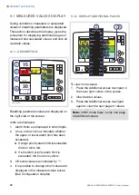
Page 54: ...ord Standby 4 8 1 START INVASIVE VENTILATION SVS 5020_XX 1 When the system is configured for invasive ventilation press the Start Standby key 1 to start ventilation or press the Start ventilation touchpad on the screen 4 8 2 START NON INVASIVE VENTILATION NIV OPTION 00 14 69 B 1 1 When the Start Standby key is pressed and the SERVO s Ventilator System is configured for NIV a waiting position dialo...

Page 55: ...g bar indicates that the selected setting is significantly beyond generally recognized safety limits this warning is accompanied by an audio signal and text message 6 Turning and pressing the Main Rotary Dial allows you to select settings and adjust values Note New settings are effective from the first breath after adjustment when the touchpad is deactivated 7 The waveforms and measured values are...

Page 56: ...d off during the disconnect phase for a maximum of 60 seconds If the patient has not been reconnected within 60 seconds alarms are activated Notes Suction Support is not available in NIV mode or when the O2 Breaths function is activated During the disconnect phase in Suction Support the nebulizer is temporarily paused When only one gas is connected an elevated oxygen level cannot be set during the...

Page 57: ...post oxygenation phase and restarts ventilation It is also possible to restart ventilation manually by pressing the Start ventilation touchpad 4 10 4 POST OXYGENATION PHASE After reconnection the ventilator will deliver the same oxygen concentration as in the preparation phase for 60 seconds After 60 seconds the system automatically returns to ventilation using the previous oxygen setting 4 10 5 C...

Page 58: ...on set by the user This temporary adjustment will be valid until the ventilator is switched off Important Before using the SERVO s Ventilator System always perform a Pre use check to make sure the O2 cell is properly calibrated SVS 6089_XX To re adjust the O2 cell 1 Press the Menu fixed key 2 Press the Biomed touchpad 3 Press the O2 cell adaptation touchpad 4 Press the Yes touchpad to perform the ...

Page 59: ...AND RECORD TABLE OF CONTENTS 60 Measured values display 5 1 62 Waveform display 5 2 64 Show event log 5 3 64 Show loops 5 4 65 Show trends 5 5 SERVO s VENTILATOR SYSTEM V7 0 User s Manual 59 Monitor and record 5 ...

Page 60: ...icates whether the upper or lower alarm limit has been exceeded If a high priority alarm limit is exceeded the box turns red If a medium priority alarm limit is exceeded the box turns yellow 3 Off scale values are indicated by 4 It is possible to change which values are displayed in the measured value boxes See Configuration chapter 5 1 2 DISPLAY ADDITIONAL PAGES SVS 5092_EN To view more values 1 ...

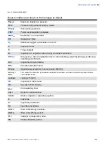
Page 61: ...pontaneous breathing and Bi Vent Ti Ttot Inspiratory Minute Volume MVi Expiratory Minute Volume MVe Spontaneous expiratory minute volume Bi Vent MVe sp The relation between spontaneous expired minute volume and total expired minute volume Bi Vent MVe sp MVe Leakage NIV Leakage Inspiratory Tidal Volume VTi Expiratory Tidal Volume VTe End expiratory flow ee Dynamic characteristics Cdyn Static compli...

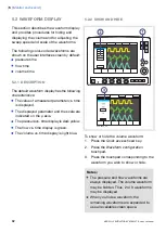
Page 62: ...he scale are indicated on the y axis The pressure vs time display is dark yellow The flow vs time display is green The volume vs time display is light blue 5 2 2 SHOW AND HIDE SVS 6029_XX To show or hide the volume waveform 1 Press the Quick access fixed key 2 Press the Waveform configuration touchpad 3 Press the touchpad corresponding to the waveform you wish to show or hide Notes The pressure an...

Page 63: ...rresponding to the waveform whose scale you wish to change or select a sweep speed 5 10 or 20 mm s 4 To adjust the scale of a waveform turn the Main Rotary Dial to the desired value or use auto scale press Auto Important MAQUET does not recommend using auto scale in Bi Vent mode when patient breathing is spontaneous on both levels SERVO s VENTILATOR SYSTEM V7 0 User s Manual 63 Monitor and record ...

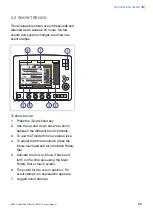
Page 64: ... 4 Use the arrows to scroll 5 4 SHOW LOOPS The Loops function provides a graphical representation of the relationship between flow volume and pressure volume SVS 6004_XX To activate the Loops function 1 Press the Quick access fixed key 2 Press the Loops touchpad 3 To close the window press Close 64 SERVO s VENTILATOR SYSTEM V7 0 User s Manual 5 Monitor and record ...

Page 65: ...scroll between the different trend channels 3 To quit the Trends Window press Close 4 To adjust the time resolution press the Hours touchpad and turn the Main Rotary Dial 5 Activate the Cursor Move it back and forth on the time axis using the Main Rotary Dial or touch screen 6 Time valid for the cursor position For event stamps an explanation appears 7 Logged event stamps SERVO s VENTILATOR SYSTEM...

Page 66: ...66 SERVO s VENTILATOR SYSTEM V7 0 User s Manual 5 Monitor and record ...

Page 67: ...ssure Control 6 5 86 Pressure Regulated Volume Control 6 6 89 Pressure Support 6 7 92 Spontaneous CPAP 6 8 94 SIMV 6 9 103 Bi Vent 6 10 106 Non Invasive Ventilation 6 11 110 Backup ventilation 6 12 113 Ventilatory parameters overview 6 13 116 Special functions 6 14 SERVO s VENTILATOR SYSTEM V7 0 User s Manual 67 Ventilation modes and functions 6 ...

Page 68: ...ers are based on either I E Ratio or Inspiration Time 6 1 1 WARNINGS Note Not all warnings apply to all modes WARNINGS Be sure to set alarm limits as appropriate for each mode It is especially Minute Volume Alarm Apnea time Self triggering should be avoided Do not set the trigger sensitivity too high To protect the patient s lungs from excessive pressure it is important to set the upper pressure l...

Page 69: ...trolled ventilation 2 supported ventilation or 3 spontaneous breathing CPAP It also allows for combined ventilatory control or support Spontaneous breathing efforts are sensed during controlled ventilation e g Volume Control Mandatory ventilation can be used during supported spontaneous breathing e g the enhanced SIMV functionality SERVO s VENTILATOR SYSTEM V7 0 User s Manual 69 Ventilation modes ...

Page 70: ...e 3 Early inspiratory pause pressure 4 End inspiratory pause pressure 5 Early expiratory pressure 6 End expiratory pressure FLOW TIME WAVEFORM 7 Peak inspiratory flow 8 Zero flow phase 9 Peak expiratory flow 10 Slope decelerating expiratory limb 11 End expiratory flow VOLUME TIME WAVEFORM 12 Start of inspiration 13 The slope represents current delivery of inspiratory tidal volume 14 End inspiratio...

Page 71: ...nspiration 2 Peak inspiratory pressure 3 End expiratory pressure FLOW TIME WAVEFORM 4 Peak inspiratory flow 5 End inspiratory flow 6 Peak expiratory flow 7 End expiratory flow VOLUME TIME WAVEFORM 8 Start of inspiration 9 End inspiration 10 End expiration SERVO s VENTILATOR SYSTEM V7 0 User s Manual 71 Ventilation modes and functions 6 ...

Page 72: ... possible to set trigger sensitivity 20 10 0 6 Trigg Pressure Trigg Flow WHITE GREEN RED The trigger sensitivity bar has different colors based on the setting A green bar indicates a normal setting for flow triggering The risk of self triggering increases when the bar is red A white bar indicates pressure triggering WARNING If the trigger sensitivity is set too high a self triggering auto triggeri...

Page 73: ...ger sensitivity level below zero 0 the ventilator senses deviations in the pressure below PEEP created by the patient The pressure below PEEP required to initiate a breath is shown when the setting is made The further to the left on the scale the more effort is required to trigger 6 3 2 INSPIRATORY RISE TIME t 100 Time to peak inspiratory flow or pressure at the start of each breath as a percentag...

Page 74: ... increased from the default setting and to give more comfort to the patient 6 3 3 PEEP PEEP SVX 646_EN A Positive End Expiratory Pressure is maintained in the alveoli and may prevent the collapse of the airways For Positive End Expiratory Pressure setting ranges see section Breathing parameters default values allowed settings standard configuration on page 152 6 3 4 I E RATIO INSPIRATION TIME The ...

Page 75: ...SIMV mode is selected since there is no need to set Breath cycle time when Inspiration time is directly set The configuration is done by a service technician with a service card 6 3 5 INSPIRATORY CYCLE OFF SVX 205_XX Inspiratory Cycle off is the point at which inspiration changes to expiration in spontaneous and supported modes of ventilation A decrease of the inspiratory flow to a preset level ca...

Page 76: ...Pressure Support PS Pressure Support level above PEEP is the set inspiratory pressure support level for triggered breaths in Pressure Support SIMV modes and Bi Vent 6 3 9 O2 CONCENTRATION The setting range for the gas mixer is 21 O2 to 100 O2 The alarm limits are automatically set at approximately 5 O2 above or below the set concentration value The alarm is delayed 40 seconds after changing the O2...

Page 77: ...is not available after a Pre use check changing of patient category admitting a new patient use of the same ventilation mode for more than 24 hours or after start up cold start of the system When Previous Mode is activated during Backup ventilation the ventilator returns to the mode that was active before Support mode was initiated A recall of previous settings is only possible after a change of v...

Page 78: ...ependent on the tidal volume inspiration time and the resistance and compliance of the respiratory system The set tidal volume will always be delivered An increase in the resistance and decrease in compliance will lead to an increased airway pressure To protect the patient s lungs from excessive pressure it is very important to set the upper pressure limit to a suitable value 6 4 2 FLOW ADAPTATION...

Page 79: ...orm show some practical consequences of this enhanced functionality the top waveform shows the trace for a normal Volume Controlled breath the second waveform shows a situation when inspiration is prematurely interrupted as the set tidal volume has been delivered the third waveform shows a situation where the patient maintains a flow rate higher than the calculated target value The set Tidal Volum...

Page 80: ...ort during the inspiratory period the ventilator will switch to Pressure Support to satisfy the patient s flow demand Expiration starts When the preset tidal volume is delivered and after the preset pause time When the flow returns to the set value after the preset tidal volume is delivered and after the preset pause time on demand support The patient is however always guaranteed an expiration tim...

Page 81: ...n touchpad Press Accept Volume Control without flow adaptation The ventilator delivers volume strictly according to the settings To ventilate with Volume Control without flow adaptation Press the Volume control without flow adaptation touchpad Press Accept Note Set trigger sensitivity at an adequate level A patient who needs more ventilation may increase the breathing frequency instead of increasi...

Page 82: ...iratory limb 6 End expiratory flow Notes Flow adaptation is not enabled in Volume Control with decelerating flow Set trigger sensitivity at an adequate level A patient who needs more ventilation may increase the breathing frequency instead of increasing the flow during inspiration The default setting of Pause time is 0 s 82 SERVO s VENTILATOR SYSTEM V7 0 User s Manual 6 Ventilation modes and funct...

Page 83: ...ce and resistance in the patient tube system and airways This means that the Tidal Volume can vary Pressure Controlled mode is preferred when there is leakage in the breathing system e g due to uncuffed endotracheal tube or in situations when the maximum airway pressure must be controlled The flow during inspiration is decelerating The patient can trigger extra breaths If the patient tries to exha...

Page 84: ...g flow 2 The preset pressure level is controlled by the ventilator The resulting volume depends on the set pressure level inspiration time and the patient s lung mechanical properties during each breath with a decelerating flow 3 Inspiration starts according to the preset frequency or when the patient triggers Expiration starts After the termination of preset inspiration time If the upper pressure...

Page 85: ...evel the expiratory valve opens and regulates the pressure down to the set inspiratory pressure level SVX 9009_EN Upper pressure Limit t If the pressure increases to the set upper pressure limit e g the patient is coughing the expiratory valve opens and the ventilator switches to expiration SERVO s VENTILATOR SYSTEM V7 0 User s Manual 85 Ventilation modes and functions 6 ...

Page 86: ... Tidal Volume or Minute Volume The following parameters are set 1 Tidal Volume ml or Minute Volume l min 2 Respiratory Rate b min 3 PEEP cmH2O 4 Oxygen concentration 5 I E ratio Insp time 6 Inspiratory rise time s 7 Trigg Flow Trigg Pressure SVS 5035_XX The ventilator delivers a pre set Tidal Volume The pressure is automatically regulated to deliver the pre set volume but limited to 5 cmH2O below ...

Page 87: ...ant during each breath but automatically adapts in small increments breath by breath to match the patient s lung mechanical properties for target volume delivery 3 Inspiration starts according to a preset frequency or when the patient triggers Expiration starts After the termination of preset inspiration time If the upper pressure limit is exceeded SERVO s VENTILATOR SYSTEM V7 0 User s Manual 87 V...

Page 88: ...re of this breath is then used as the pressure level for the following breath An alarm is activated if the pressure level required to achieve the set target volume cannot be delivered due to a lower setting of the upper pressure limit 5 cmH2O 88 SERVO s VENTILATOR SYSTEM V7 0 User s Manual 6 Ventilation modes and functions ...

Page 89: ... are set 1 PS Pressure Support level above PEEP cmH2O 2 PEEP cmH2O 3 Oxygen concentration 4 Inspiratory rise time s 5 Trigg Flow Trigg Pressure 6 Inspiratory Cycle off 7 PC above PEEP cmH2O in backup ventilation 8 Resp Rate b min in backup ventilation 9 I E Ti s in backup ventilation depending on configuration SVS 5044_XX During Pressure Supported ventilation the patient regulates the respiratory ...

Page 90: ... Pressure Support the Inspiratory rise time should normally be increased 70 Inspiratory Cycle off is important for the patient s comfort and ventilator synchronization with the patient Inspiratory Cycle off is the point when inspiration switches to expiration E g for a patient with expiratory resistance the inspiratory Cycle off should be set to a high value to guarantee enough time for expiration...

Page 91: ... is constant the flow will decrease until the Inspiratory Cycle off is reached Expiration starts a When the inspiratory flow decreases below a preset fraction of the inspiratory peak flow Inspiratory cycle off b If the upper pressure limit is exceeded c If the maximum time for inspiration is exceeded d If the flow drops to a flow range between 25 of the peak flow and lower limit for Inspiratory Cy...

Page 92: ...continuous positive pressure is maintained in the airways Properly set this may prevent collapse of airways Inspiration starts upon patient effort Expiration starts as for Pressure Support above Always set the Apnea time appropriately to the individual patient situation If the apnea alarm limit is reached the ventilator will automatically switch to backup ventilation The alarm should alert staff t...

Page 93: ...set to zero Inspiration starts upon patient effort Expiration starts When the inspiratory flow decreases below a preset fraction of the inspiratory peak flow Inspiratory cycle off If the upper pressure limit is exceeded Maximum time for inspiration is exceeded SERVO s VENTILATOR SYSTEM V7 0 User s Manual 93 Ventilation modes and functions 6 ...

Page 94: ... the Minute Volume configuration the Tidal Volume is determined by Minute Volume divided by SIMV rate The Breath cycle time is the length of the mandatory breath in seconds For example A SIMV rate of 6 a breath cycle time of 3 seconds with an I E ratio of 1 2 means that the inspiration will take 1 second and the expiration 2 seconds SIMV Period 10 sec SIMV Cycle SIMV Period Spon Period 3 7 3 SVX 9...

Page 95: ...Tidal volume Minute volume X X X SIMV rate X 1 X 1 X 1 Breath cycle time X X X I E ratio Inspiration time X X X Insp rise time X Pause time 1 Only when the ventilator is configured for I E ratio setting SERVO s VENTILATOR SYSTEM V7 0 User s Manual 95 Ventilation modes and functions 6 ...

Page 96: ... Insp time 6 Pause time s 7 Inspiratory rise time s 8 Breath cycle time s Note The touchpad Breath cycle time is not shown when an SIMV mode is selected and the ventilator is configured for inspiration time 9 Trigg Flow Trigg Pressure 10 Inspiratory Cycle off 11 PS Pressure support above PEEP cmH2O SVS 5059_XX 96 SERVO s VENTILATOR SYSTEM V7 0 User s Manual 6 Ventilation modes and functions ...

Page 97: ...gger attempt within a time window equal to 90 of the set Breath cycle time a mandatory breath is delivered The Breath cycle time is the total time for one mandatory breath 3 The mandatory breath is defined by the basic settings mode of ventilation breath cycle time respiratory pattern and volumes pressures 4 The spontaneous pressure supported breaths are defined by the setting for Pressure Support...

Page 98: ... patterns are available in Volume Control Automode VC VS and SIMV VC PS 1 3 2 4 1 Volume control with flow adaptation 2 Volume control without flow adaptation 3 Volume control with decelerating flow 4 Flow pattern See section Volume control with alternative flow patterns on page 81 for more information 98 SERVO s VENTILATOR SYSTEM V7 0 User s Manual 6 Ventilation modes and functions ...

Page 99: ...I E ratio Insp time 6 Inspiratory rise time s 7 Breath cycle time s Note The touchpad Breath cycle time is not shown when an SIMV mode is selected and the ventilator is configured for inspiration time 8 Trigg Flow Trigg Pressure 9 Inspiratory Cycle off 10 PS Pressure Support level above PEEP cmH2O SVS 5054_XX SERVO s VENTILATOR SYSTEM V7 0 User s Manual 99 Ventilation modes and functions 6 ...

Page 100: ...gger attempt within a time window equal to 90 of the set Breath cycle time a mandatory breath is delivered The Breath cycle time is the total time for one mandatory breath 3 The mandatory breath is defined by the basic settings mode of ventilation breath cycle time respiratory pattern and volumes pressures 4 The spontaneous pressure supported breaths are defined by the setting for Pressure Support...

Page 101: ...Insp time 6 Inspiratory rise time s 7 Breath cycle time s Note The touchpad Breath cycle time is not shown when an SIMV mode is selected and the ventilator is configured for inspiration time 8 Trigg Flow Trigg Pressure 9 Inspiratory Cycle off 10 PS Pressure Support level above PEEP cmH2O SVS 5051_XX SERVO s VENTILATOR SYSTEM V7 0 User s Manual 101 Ventilation modes and functions 6 ...

Page 102: ...gger attempt within a time window equal to 90 of the set Breath cycle time a mandatory breath is delivered The Breath cycle time is the total time for one mandatory breath 3 The mandatory breath is defined by the basic settings mode of ventilation breath cycle time respiratory pattern and volumes pressures 4 The spontaneous pressure supported breaths are defined by the setting for Pressure Support...

Page 103: ...e support The following parameters are set 1 Pressure high PHigh for the higher pressure level cmH2O 2 PEEP for the lower pressure level cmH2O 3 Oxygen concentration 4 Time at the higher pressure THigh level s 5 Time at the lower pressure TPEEP level s 6 Inspiratory rise time s 7 Trigg Flow Trigg Pressure 8 Inspiratory Cycle off 9 PS Pressure Support level above PHigh cmH2O 10 PS Pressure Support ...

Page 104: ...umes respiratory rate mean pressure and end expiratory pressure In accordance to this associated alarms are also handled for every Bi Vent cycle At extreme settings the update of measured values and alarms will show a mandatory frequency dependence even in the face of preserved spontaneous breathing As a result of switching between two different pressure levels the tidal volumes may vary significa...

Page 105: ...pressure levels These basic levels are individually set as well as the time in seconds at each level The ventilator always tries to synchronize with the patient s breathing 1 Bi Vent cycle THigh TPEEP 2 PEEP 3 PHigh 4 PS above PEEP 5 PS above PHigh SERVO s VENTILATOR SYSTEM V7 0 User s Manual 105 Ventilation modes and functions 6 ...

Page 106: ...ure a constant disconnect flow while ventilation is paused High flow and Low flow or as a way to avoid pausing ventilation in case of high leakage Disabled For NIV disconnect function settings see Functions in ventilation modes on page 154 WARNINGS Avoid high inspiratory pressure as it may lead to gastric overdistension and risk of aspiration It may also cause excessive leakage The dead space will...

Page 107: ...r Important The mask must be applied correctly in order to avoid leakage Selection of a mask must take into consideration its proper size and accurate adaptation to the patient CO2 rebreathing will increase during NIV and use of a face mask Read about alarm settings on page 126 See also Set Ventilation Mode on page 52 SERVO s VENTILATOR SYSTEM V7 0 User s Manual 107 Ventilation modes and functions...

Page 108: ...ad to start the ventilation During NIV the ventilator automatically adapts to variations in leakage in order to maintain the required pressure and PEEP level If leakage is excessive the ventilator will issue a high priority alarm and deliver a flow according to settings Ventilation will resume automatically if the leakage decreases Ventilation can also be started manually by pressing the Resume ve...

Page 109: ...urned off during 120 seconds Press the Start ventilation touchpad to start the ventilation During NIV the ventilator automatically adapts to variations in leakage in order to maintain the required pressure and PEEP level If leakage is excessive the ventilator will issue a high priority alarm and deliver a flow according to settings Ventilation will resume automatically if the leakage decreases Ven...

Page 110: ...ve PEEP cmH2O in backup ventilation Pressure Support 2 Resp Rate b min in backup ventilation 3 I E Ti s in backup ventilation depending on configuration NO PATIENT EFFORT In case of apnea the ventilator will switch to backup ventilation according to the backup settings at the end of the set apnea time The Apnea time is set in the Alarm Profile window Backup is indicated in the active Ventilation m...

Page 111: ...mode The ventilator will remain in backup ventilation until a choice is made REVIEW VENTILATION SETTINGS Press Review vent settings in the Backup ventilation window to return to the Set Ventilation Mode window 3 2 1 The following functions are available 1 Previous Mode recalls the previous accepted ventilation mode 2 Cancel closes the Set Ventilation Mode window without changes being applied i e v...

Page 112: ...on when running not in Standby 1 To disable backup ventilation 1 Press the Backup ventilation touchpad 2 A confirmation dialog Do you really want to deactivate backup ventilation is displayed Confirm by pressing Yes 3 Backup ventilation off is displayed on the Ventilation mode touchpad 4 Press Accept in the Set Ventilation Mode window The backup function is automatically re activated if the user C...

Page 113: ...w or pressure at the start of each breath as a percentage of the breath cycle time or in seconds s 6 I E ratio I E Inspiration time Pause time Expiration time 7 Inspiration time Ti Time for active flow or pressure delivery to the patient s 8 Pause time Tpause Time for no flow or pressure delivery or s 9 Trigger sensitivity a Below zero Trigger sensitivity is pressure dependant The pressure below P...

Page 114: ...reath in SIMV inspiratory pause expiratory Set in seconds 13 SIMV rate Rate of controlled mandatory breaths b min O2 concentration O2 Conc O2 concentration in inspiratory gas not shown in the figure 114 SERVO s VENTILATOR SYSTEM V7 0 User s Manual 6 Ventilation modes and functions ...

Page 115: ...ng the THigh period in Bi Vent cmH2O 17 Pressure Support above PEEP PS above PEEP Inspiratory pressure support level for breaths triggered during the TPEEP period in Bi Vent cmH2O 18 Pressure high PHigh Positive End Expiratory Pressure at the upper level in Bi Vent cmH2O 19 PEEP Positive End Expiratory Pressure at the lower level in Bi Vent cmH2O SERVO s VENTILATOR SYSTEM V7 0 User s Manual 115 Ve...

Page 116: ...ilator will initiate a new breath cycle according to the current ventilator settings O2 BREATHS SVS 5030_XX This function delivers 100 oxygen for 1 minute After this time the oxygen concentration will return to the pre set value The oxygen breaths can be interrupted by repressing the O2 breaths fixed key during the 1 minute interval 116 SERVO s VENTILATOR SYSTEM V7 0 User s Manual 6 Ventilation mo...

Page 117: ...hown on the PEEP numerical value INSPIRATORY HOLD SVS 5031_XX Inspiratory hold is activated by manually pressing the fixed key The maximum time is 30 seconds The inspiratory and expiratory valves close after inspiration This function can provide an exact measurement of the end inspiratory lung pressure It can be used during x ray or to determine Plateau pressure or together with expiratory hold ca...

Page 118: ...118 SERVO s VENTILATOR SYSTEM V7 0 User s Manual 6 Ventilation modes and functions ...

Page 119: ...7 ALARMS TABLE OF CONTENTS 120 Introduction 7 1 122 Handling Alarms 7 2 126 Alarm Settings for Breathing Parameters 7 3 SERVO s VENTILATOR SYSTEM V7 0 User s Manual 119 Alarms 7 ...

Page 120: ...The Power Supply chapter describes power supply related alarms The System Messages chapter lists all alarms along with possible causes and remedies WARNINGS The default setting of the high airway pressure alarm is 40 cmH2O It is important to adjust this setting as appropriate to avoid excessive airway pressures A potential hazard can arise if different default alarm settings are used on ventilator...

Page 121: ...eed alarm according to IEC 60601 1 8 and it is recommended that users establish a Pre use check routine for this application 7 1 2 VISUAL ALARM DISPLAY SVS 6002_XX When an alarm is activated the following information is supplied on the screen 1 A text message explaining the cause of the alarm flashes in the alarm message area The alarm with highest priority is displayed first 2 The corresponding m...

Page 122: ...than one alarm is active view the Current Alarms Window by 1 Press the bell s in the alarm message touchpad All alarms up to 10 listed by priority are shown in a dynamic window that will be updated if more alarms occur while the window is open 2 View the current alarms 3 Press the History touchpad The previous 16 alarm dependent events are listed chronologically with the most recent event at the b...

Page 123: ...ng Medium Priority alarms display an Audio off message when activated Air Supply Pressure Low O2 Supply Pressure Low Battery Operation For these alarms you can silence the audio signal even if the alarm condition is not resolved However the system will eventually reactivate the alarm Using the Audio Pause Key SVX 5098_EN Pressing the Audio Pause fixed key for less than two seconds has the followin...

Page 124: ...along with the time remaining in the silent period are displayed in the message area 3 Pressing the Audio Pause key again for less than two seconds will now restart the silent period for two additional minutes from when the user last pressed the key 4 Latched alarms are reset if the alarm condition has ceased SVX 5098_EN When the alarms are pre silenced pressing and holding the Audio Pause key aga...

Page 125: ...ity alarms are not latched The fixed key Audio Pause resets latched alarms and clears the alarm message from the screen Note The NIV alarm Leakage out of range is not latched 7 2 6 PERMANENTLY SILENCING ALARMS To permanently silence certain alarms in NIV mode 1 Press the Alarm Profile fixed key 2 Press the touchpad corresponding to one of the following alarms Minute Volume Respiratory Rate PEEP 3 ...

Page 126: ...et to their default values when restarting the ventilator admitting a new patient changing type of ventilation option the ventilator has been totally without power for more than 2 minutes 7 3 4 LIST OF ALARM SETTINGS Automatically Set These settings are determined automatically by the ventilator based on the related parameter settings O2 concentration high based on O2 concentration setting O2 conc...

Page 127: ...8 OPTIONAL ACCESSORIES TABLE OF CONTENTS 128 General 8 1 128 Active humidifiers 8 2 129 Nebulizers 8 3 130 Compressor Mini 8 4 SERVO s VENTILATOR SYSTEM V7 0 User s Manual 127 Optional Accessories 8 ...

Page 128: ...m usage time according to filter specification whichever comes first CAUTION If the Aeroneb nebulizer is used with active humidification then the particle size of the medication may be affected Important Use only tubes recommended by MAQUET Soft tubing may negatively affect the performance of the ventilator If a single heated breathing circuit is used in the system a water trap must be used on the...

Page 129: ... for instructions WARNINGS Disconnect the Servo Humidifier HME during nebulization otherwise the humidifier may become blocked or the drug may be trapped in the humidifier Do not use the nebulizer without a filter e g Servo Duo Guard connected to the expiratory inlet of the ventilator During nebulization carefully monitor the airway pressure Increased airway pressure could result from a clogged fi...

Page 130: ...a central gas supply or gas cylinders Using surrounding air the compressor collects and stores gas for direct use with the SERVO s Ventilator system as long as the ventilator is active Please refer to the Compressor Mini User s Manual 130 SERVO s VENTILATOR SYSTEM V7 0 User s Manual 8 Optional Accessories ...

Page 131: ...LE OF CONTENTS 132 Introduction 9 1 133 High priority alarms 9 2 136 Medium priority alarms 9 3 138 Low priority alarms 9 4 138 Technical error messages 9 5 SERVO s VENTILATOR SYSTEM V7 0 User s Manual 131 System messages 9 ...

Page 132: ...he patient from the ventilator when performing operations that increase risk to the patient such as replacing the O2 cell CAUTION Do not lift or disconnect the expiratory cassette when the ventilator is operating instead you may do this in Standby Note Most technical errors require the attention of a service technician 132 SERVO s VENTILATOR SYSTEM V7 0 User s Manual 9 System messages ...

Page 133: ...reathing system Check trigger sensitivity setting Check alarm limit settings Preset or default alarm limit exceeded Increased patient activity Ventilator self triggering autocycling Improper alarm limit setting Expiratory Minute Volume High Check patient Check cuff pressure Check patient breathing system perform leakage test if necessary Check pause time and graphics to verify Consider increased v...

Page 134: ...has only triggered a single breath to interrupt each of two consecutive backup periods No consistent patient effort Check patient and breathing system Check ventilator settings An apnea has caused the ventilator to switch to backup ventilation No patient effort Check O2 cell sensor and connection O2 cell sensor missing or disconnected O2 cell sensor failure Check air supply Perform a Pre use check...

Page 135: ...ssure for the safety valve Safety valve test failed Restart the ventilator and perform a Pre use check Check ventilator settings Software error memory corrupt Settings lost Restart ventilator Perform a Pre use check Change the expiratory cassette and perform a Pre use check Contact a service technician Technical problem with the expiratory cassette Technical error in Expiratory cassette Restart th...

Page 136: ...ange Exp cassette exchanged Change ventilator settings Combination of settings exceeds the allowable inspiration flow range Inspiratory flow overrange Check fan operation Check the operating temperature Clean the fan filter in the patient unit Temperature inside the ventilator is too high Internal temperature High Check patient and breathing system Check mask prongs size and patient fit Check the ...

Page 137: ...ge at patient connection cuff tracheal tube PEEP Low Check ventilator settings It is not possible to reach the Set volume in PRVC due to restrictions imposed by the set upper pressure limit Set high pressure alarm limit this limits the regulatory pressure used in PRVC Regulation pressure limited Attend to the patient Check the trigger setting Respiratory rate too high Auto triggering Respiratory R...

Page 138: ...n Audible alarm loudspeaker error 28 20004 Contact a service technician Internal clock error 41 Contact a service technician Internal communication error 25 33 35 50 10002 20001 Contact a service technician Barometer error 38 39 Contact a service technician Alarm output connection error 46 Contact a service technician Fixed battery missing 47 Contact a service technician Timeout error 8 9 48 49 Re...

Page 139: ...LE OF CONTENTS 140 Introduction 10 1 140 Access the Start Up Configuration 10 2 141 Edit the Start up Configuration 10 3 142 Start MCare Remote Service 10 4 SERVO s VENTILATOR SYSTEM V7 0 User s Manual 139 Start up configuration 10 ...

Page 140: ...up ventilation Disabled or Enabled NIV disconnect function Low flow High flow or Disabled Extended leakage test during pre use check Volume Control with alternative flow patterns 10 2 ACCESS THE START UP CONFIGURATION SVS 9046 Note The ventilator must be in Standby 1 Press the Menu fixed key 2 Press the Biomed touchpad and enter the access code the factory setting is 1973 The Biomed submenu consis...

Page 141: ...lation mode settings 5 Press the appropriate touchpad to change the settings Note Press Restore mode settings to restore factory default settings 6 Press Next to view a summary of the start up configuration 7 Press Accept to save the start up settings Note The ventilator must be restarted to activate the new settings 10 3 1 PROCEDURE DIAGRAM EDIT THE START UP CONFIGURATION SVS 9045_XX SERVO s VENT...

Page 142: ...rvice is activated Make sure the network cable is connected and Progress Waiting for transfer followed by Sending log files 1 3 When the transfer is finished the message The file transfer is completed MCare Remote Service will be deactivated Disconnect the network cable Accept the dialog by pressing OK and the MCare Remote Service is deactivated WARNING Always disconnect the network cable before s...

Page 143: ...ters default values allowed settings standard configuration 11 8 153 Alarms 11 9 154 Functions in ventilation modes 11 10 155 Trend function 11 11 156 Log function 11 12 156 Immediate functions 11 13 156 Communication interface 11 14 157 Service 11 15 157 Accessories 11 16 158 Pollution control 11 17 159 Information required by ISO 80601 2 12 11 18 161 UDI Label 11 19 SERVO s VENTILATOR SYSTEM V7 ...

Page 144: ...the enclosure as well as dripping water with a flow rate of 1 ml min for ten minutes Noise A weighted sound pressure level LpA 41 dB measured at a distance of 1 m A weighted sound power level LWA 50 dB 11 1 2 OPERATING CONDITIONS Operating Temperature range 10 to 40 C Relative humidity 15 to 95 non condensing Atmospheric pressure 660 to 1060 hPa Lowest pressure in patient circuit 400 cmH2O Mechani...

Page 145: ...tteries External 12V DC 12 0 V 15 0 V DC 10 A Fuse 10 A 32 V Miniblade 12V Information regarding connector wiring and EMC performance is available from MAQUET CAUTION When using external 12V DC at least two installed battery modules are required to ensure proper operation Max power consumption At 110 120V 2A 190VA 140W At 220 240V 1A 190VA 140W On Off switch Set to On when off battery continues to...

Page 146: ...be detectable 3 Oxygen H2O 20 mg m 3 Oil 0 3 mg m 3 Inlet gas Pressure 2 0 6 0 kPa x 100 29 87 psi max 60 l min Connection standards available AGA DISS NIST or French Unavailable gas loss of gas pressure The flow from an unavailable gas air or O2 is automatically compensated for so that the patient gets the preset volume and pressure 11 2 3 PATIENT SYSTEM CONNECTORS Conical fittings mm Male 22 and...

Page 147: ...nce compensation is activated Default settings unless otherwise specified All measured preset and indicated flows and volumes are referenced to BTPS see chapter Definitions on page 163 All measured inlet gas pressures and flows are referenced to STPD see chapter Definitions on page 163 Humidifier water level is between 50 and 100 of the maximum level Set I E is less than 1 1 Set ventilatory freque...

Page 148: ...n Compliance 0 5 5 0 ml cmH2O at airway pressure 50 cmH2O The limits used in the presentation under Status Patient Circuit are adjusted for measurement inaccuracy 11 5 INSPIRATORY CHANNEL Pressure drop Maximum 6 cmH2O at a flow of 60 l min Internal compressible factor Maximum 0 1 ml cmH2O Gas delivery system Microprocessor controlled valves Gas delivery device Flow range 0 3 3 l s Inaccuracy 0 1 m...

Page 149: ...me Range 0 60 l min Inaccuracy 0 18 l min 8 of actual value 5 NIV 10 Expiratory Tidal Volume Range 0 2000 ml Inaccuracy 4 ml 8 of actual volume for VT 100 ml 2000 ml Respiratory rate Range 1 160 b min Inaccuracy 1 b min O2 Concentration Range 0 100 Inaccuracy 2 5 vol 2 5 of actual gas concentration Stability within 8 hour period 2 5 volume 2 5 of actual gas concentration The inaccuracy of the meas...

Page 150: ...measured and calculated values displayed or used for control have in some cases been subjected to filtering and smoothing techniques This is done to capture the important patterns in the data while excluding noise and make the data shown clinically relevant These techniques are part of the inaccuracy specified in the technical data 150 SERVO s VENTILATOR SYSTEM V7 0 User s Manual 11 Technical data...

Page 151: ... 1 10 4 1 1 2 I E ratio in backup 1 70 30 Inspiratory cycle off of peak flow 10 70 50 Inspiratory cycle off of peak flow in NIV 0 20 5 Inspiratory rise time 0 0 4 0 15 Inspiratory rise time s 0 0 4 0 2 Inspiratory rise time s in NIV 3 3 Maximum inspiratory flow l s 120 Maximum permitted absolute pressure cmH2O 32 Maximum permitted absolute pressure in NIV cmH2O 0 5 60 7 5 Minute Volume l min VC Mo...

Page 152: ... level above PEEP in backup cmH2O 5 32 PEEP 5 Pressure level above PEEP in NIV backup cmH2O 0 120 PEEP 0 PS above PEEP in Bivent cmH2O 0 120 PHigh 0 PS above Phigh in Bivent cmH2O 4 100 15 Resp rate in backup 1 60 5 SIMV frequency b min 0 2 10 2 Thigh s 0 1 5 0 9 Ti s 0 1 5 0 9 Ti in backup s 100 2000 500 Tidal Volume ml 100 2000 500 Tidal volume in backup ml 0 30 10 Tpause 0 1 5 0 4 Tpause s 0 2 ...

Page 153: ... 30 Respiratory rate upper limit b min No Set value 5 vol O2 concentration high No Set value 5 vol or 18 vol O2 concentration low 2 0 kPa x 100 or 6 0 kPa x 100 Gas supply No Obstruction leading to constant high airway pressure PEEP 15 cmH2O during 2 breaths or 5 seconds whichever is greater 15 1 5 s if less 2 breaths are triggered High continuous pressure 6 If Paw rises 6 cmH2O above the set limi...

Page 154: ...mit 50 Respiratory rate Upper alarm limit 40 Respiratory rate Lower alarm limit 40 End Expiratory Pressure Upper alarm limit Mean End Expiratory Pressure 5 cmH2O End Expiratory Pressure Lower alarm limit Mean End Expiratory Pressure 3 cmH2O 11 9 3 ALARMS MISCELLANEOUS Audio Pause Alarm silence reset Two minute silence and reset of latched alarms 11 10 FUNCTIONS IN VENTILATION MODES Maximum inspira...

Page 155: ...ute Volume MVe Expired Minute Volume Leakage Leakage fraction VTi Inspired Tidal Volume VTe Expired Tidal Volume ee End Expiratory Flow O2 Measured Oxygen Concentration Cdyn Dynamic Characteristics Cstatic Static Compliance Ri Inspiratory Resistance Re Expiratory Resistance WOB v Work of Breathing ventilator WOB p Work of Breathing patient E Elastance P0 1 P0 1 SBI Shallow Breathing Index SERVO s ...

Page 156: ...rface Emulator CIE Information regarding connector wiring and EMC performance is available from MAQUET Communication Interface Emulator CIE A protocol for data communication with external devices The SERVO s Ventilator System software v7 0 uses CIE Protocol version 004 This protocol is compatible with previous versions although all data may not be available Alarm Output Connection Option Isolated ...

Page 157: ...ormation 11 16 ACCESSORIES 11 16 1 MOBILE CART OPTION Weight kg 25 Dimensions mm W 500 x L 650 x H 830 with handles 1030 11 16 2 SHELF BASE OPTION Weight kg 0 1 Dimensions mm W 80 X L 160 X H 8 11 16 3 COMPRESSOR MINI OPTION Dimensions mm W 430 x D 330 x H 250 Weight approximate kg lbs 26 70 Power supply 115 V AC 60 Hz single phase 220 240 V AC 50 60 Hz single phase Compressor capacity Continuous ...

Page 158: ...China Electronic Industry Standard SJ T11364 2006 Hazardous substances PBDE PBB Cr 6 Cd Hg Pb Parts 0 0 X 0 0 0 Metal parts 0 0 0 0 0 0 Plastic and polymeric parts 0 0 0 0 0 X Electrical components 0 0 0 0 0 0 LCD display 0 Indicates that this toxic or hazardous substance contained in all of the homogeneous materials for this part is below the limit and meets the requirement in SJ T11363 2006 X In...

Page 159: ...rt 3 0 of set value for VT 300 ml 3 0 of set value for 100 ml VT 300 ml 11 18 2 PRESSURE CONTROLLED BREATH TYPE Characteristics valid for patient categories and circuit configurations intended to provide the indicated tidal volume at conditions specified in ISO 80601 2 12 table 201 104 Maximum inaccuracy of airway pressure PAW at the end of the inspiratory phase 1 cmH2O 5 of set value for VT 300 m...

Page 160: ...or oxygen concentration to change from 21 to 90 Maximum 25 s at VT 500 ml for patient categories and circuit configurations intended to provide VT 300 ml Maximum 35 s at VT 150 ml for patient categories and circuit configurations intended to provide 100 ml VT 300 ml 160 SERVO s VENTILATOR SYSTEM V7 0 User s Manual 11 Technical data ...

Page 161: ...each referred to by their AI number Application Identifier AI GTIN Global Trade Item Number 01 Part number 241 Batch no 10 Manufacturing date YYMMDD 11 Exp date YYMMDD 17 Revision 20 Serial number 21 Count of items 30 The GTIN consists of four parts 0 732571 000021 2 a b c d a Package level b GS 1 company prefix c Item reference d Check digit SERVO s VENTILATOR SYSTEM V7 0 User s Manual 161 Techni...

Page 162: ...162 SERVO s VENTILATOR SYSTEM V7 0 User s Manual 11 Technical data ...

Page 163: ...piration max 30 seconds Measures plateau pressure Inspiratory cycle off Fraction of maximum flow at which inspiration should switch to expiration Inspiratory rise time Time to full inspiratory flow or pressure at the start of each breath as a percentage or in seconds of the breath cycle time or s Leakage leakage in relation to inspiratory flow Minute Volume Volume per minute or target volume l MVe...

Page 164: ...service software card SIMV Synchronized Intermittent Mandatory Ventilation SIMV rate Rate of controlled mandatory breaths b min Start breath Manually triggered set breath STPD Standard Temperature and Pressure Dry All measured inlet gas pressures and flows at 20 C standard temperature standard pressure 101 3 kPa and relative humidity 0 dry T Time Tc Time constant Ti Inspiration time Ti Ttot Duty c...

Page 165: ...Fixed keys 13 1 167 Special function keys 13 2 168 Quick access key 13 3 169 Main screen key 13 4 170 Menu Key 13 5 172 Biomed menu standby mode 13 6 174 Screen touchpads 13 7 SERVO s VENTILATOR SYSTEM V7 0 User s Manual 165 Appendix User interface 13 ...

Page 166: ...file setup Possible selections Pressure upper Minute volume lower and upper Respiratory rate lower and upper End expiratory pressure lower and upper Alarm sound level 10 100 Note In NIV the alarm sound can be permanently silenced audio off Alarm profile The trend graph appears when the Trend key is pressed Data can be recorded over a period of time up to 24 hours The time resolution is displayed i...

Page 167: ...activated by manually pressing the Exp hold key The maximum time is 30 seconds The inspiratory and expiratory valves close after expiration This function can provide an exact measurement of the end expiratory lung pressure It can be used for static compliance measurement and to determine the total PEEP Exp hold Inspiratory hold is activated by pressing the Insp hold key The maximum time is 30 seco...

Page 168: ...ed value x axis against another measured value y axis Loops are updated breath by breath Two loops are available volume pressure flow volume Loops Waveform scaling Pressure scaling Flow scale Volume scale These three scales are set to automatic scaling by default The sweep speed mm s can be set to 10 or 20 mm s default Waveform scales Possibility to increase the space for viewing the waveform curv...

Page 169: ...screen The Main screen fixed key will return you to the Main screen cancelling current work from wherever you are in the Menu dialog windows Main screen SERVO s VENTILATOR SYSTEM V7 0 User s Manual 169 Appendix User interface 13 ...

Page 170: ...Minute volume lower and upper Respiratory rate lower and upper End expiratory pressure lower and upper Alarm sound level 10 100 Note In NIV the alarm sound can be permanently silenced audio off Alarm Profile This shows alarms that have been activated The list is in alphabetical order Alarm History Audio pause Silence or pre silence alarms Alarm Review Review trends event log or configuration Revie...

Page 171: ... Compliance Biomed Measured O2 concentration will be adapted in relation to set value Biomed O2 cell adaptation only during ventilation Locks all user input functions on the User Interface Press Main screen fixed key to unlock Panel lock SERVO s VENTILATOR SYSTEM V7 0 User s Manual 171 Appendix User interface 13 ...

Page 172: ...Functions Display service logs Possible selections 21 latest logs selected time interval Service Service log Technical alarms Test results Preventive maintenance Service report history Installation log Enters a date for the preventative maintenance into the service log Service Report PM Reset of breath counter in expiratory cassette Service Replaced Exp membrane 172 SERVO s VENTILATOR SYSTEM V7 0 ...

Page 173: ...ms Startup configuration Copy configuration to from PC card Copy configuration Date and time setup Set date and clock Change access code to Biomed menu Change access code Starts MCare Remote Service function Start MCare Remote Service SERVO s VENTILATOR SYSTEM V7 0 User s Manual 173 Appendix User interface 13 ...

Page 174: ...nds calculated inspiratory flow Mode Xxxxx When the admit patient function is activated the clinician can enter or amend patient details date of admission patient name identity number height weight date of birth Admit patient In the Status function an icon displays which power source is currently active i e Mains Ext 12 V or battery When the batteries are in use information about remaining time is...

Page 175: ...on the setting the bar is green for a normal setting for flow triggering the bar is red when there is a risk of self triggering the bar is white when pressure triggering is selected Note If there is leakage in the breathing system e g if an uncuffed endotracheal tube is used triggering will then be initiated by the system and not by the patient This should always be avoided by decreasing the trigg...

Page 176: ...176 SERVO s VENTILATOR SYSTEM V7 0 User s Manual 13 Appendix User interface ...

Page 177: ...14 CERTIFICATES TABLE OF CONTENTS 178 China 14 1 SERVO s VENTILATOR SYSTEM V7 0 User s Manual 177 Certificates 14 ...

Page 178: ...AB Manufacturer Rontgenvagen 2 SE 17154 Solna Sweden Manufacturer Manufacturer site address Maquet Shanghai Medical Equipment Co Ltd Agent for registration and after sales Room 227 2nd floor No 56 Meisheng Road Pilot Free Trade Zone Shanghai China Agent address 800 820 0207 Agent contacts 150810 IFU revise date 178 SERVO s VENTILATOR SYSTEM V7 0 User s Manual 14 Certificates ...

Page 179: ...w 36 38 Biomed 26 140 172 Bi Vent 103 BTPS 147 163 C Charging Operating time 37 Communication Interface 156 Compressor Mini 157 Copy configuration 140 D Definitions 163 Device description 6 Device description Compressor Mini 157 Mobile cart 157 Dimensions 146 Direct access knob 24 E EMC 144 Event log 64 122 156 Expiratory cassette 32 Expiratory channel 149 Expiratory hold 116 117 External 12 V 27 ...

Page 180: ...nt circuit test 50 Patient data 50 Patient range 144 Patient unit Connections and labels 28 29 Gas flow 32 Pause time T pause 113 PEEP 74 113 Power supply 35 157 Pressure Control 71 83 83 Pressure Regulated Volume Control PRVC 86 87 Pressure Support 89 Pre use check 42 Previous mode 77 PRVC 86 87 Q Quick access key Loops 168 Scales 168 R Respiratory rate 76 76 Review 170 S Service 7 157 Service Lo...

Page 181: ...ndix 165 Basic principles 16 18 21 V Ventilation Bi Vent 103 105 I E ratio inspiration time 74 Mandatory breath 95 Modes of ventilation 70 Parameters 113 Pressure Control 71 83 Pressure Support 89 PRVC 86 Settings 55 72 126 151 Set ventilation mode 52 52 SIMV 94 Spontaneous breathing CPAP 69 92 93 Supported ventilation 89 Type of ventilation 51 Volume Control 70 78 Ventilator 16 146 Ventilatory 69...

Page 182: ...182 SERVO s VENTILATOR SYSTEM V7 0 User s Manual 15 Index ...

Page 183: ...x ...

Page 184: ...ite www maquet com GETINGE GROUP is a leading global provider of products and systems that contribute to quality enhancement and cost efficiency within healthcare and life sciences We operate under the three brands of ArjoHuntleigh GETINGE and MAQUET ArjoHuntleigh focuses on patient mobility and wound management solutions GETINGE provides solutions for infection control within healthcare and conta...

Page 185: ...SERVO s VENTILATOR SYSTEM V7 0 User s Manual ...

Reviews: