background image

2

Contents

Page

Important notes

Usage for the intended purpose ...............................................................................................................4

Function ..................................................................................................................................................4

Safety note ..............................................................................................................................................4

Directives and standards

Pressure Equipment Directive 2014/34/EU ..............................................................................................5

Functional Safety acc. to IEC 61508 ........................................................................................................5

DIN EN 14597 .........................................................................................................................................5

Approvals for Marine Applications ...........................................................................................................5

ATEX (Atmosphère Explosible) .................................................................................................................5

Note on the Declaration of Conformity / Declaration by the Manufacturer    ..........................................5

Technical data

TRG 5-63, TRG 5-64, TRG 5-65, TRG 5-66, TRG 5-67 and TRG 5-68 ........................................................6

TRG 5-63, TRG 5-64, TRG 5-65, TRG 5-66, TRG 5-67 and TRG 5-68 ........................................................7

Scope of supply ......................................................................................................................................7

Tolerances of the  precision resistor according to EN 60751 ....................................................................8

Name plate / marking .............................................................................................................................8

Installation 

Dimensions TRG 5-63 and TRG 5-64 .......................................................................................................9

Key .........................................................................................................................................................9

Dimensions TRG 5-65, TRG 5-66, TRG 5-67 and TRG 5-68 ....................................................................10

Key .......................................................................................................................................................10

TRG 5-63 and TRG 5-64 ........................................................................................................................11

TRG 5-65, TRG 5-66, TRG 5-67 and TRG 5-68 .......................................................................................11

Tools .....................................................................................................................................................11

Examples of installation ........................................................................................................................12

Electrical connection

TRG 5-63, TRG 5-64, TRG 5-65, TRG 5-66, TRG 5-67 and TRG 5-68, terminal box .................................13

Key .......................................................................................................................................................13

Summary of Contents for TRG 5-6

Page 1: ...1 E N English Temperature Sensor TRG 5 6 Original Installation Instructions 818597 05 ...

Page 2: ...ical data TRG 5 63 TRG 5 64 TRG 5 65 TRG 5 66 TRG 5 67 and TRG 5 68 6 TRG 5 63 TRG 5 64 TRG 5 65 TRG 5 66 TRG 5 67 and TRG 5 68 7 Scope of supply 7 Tolerances of the precision resistor according to EN 60751 8 Name plate marking 8 Installation Dimensions TRG 5 63 and TRG 5 64 9 Key 9 Dimensions TRG 5 65 TRG 5 66 TRG 5 67 and TRG 5 68 10 Key 10 TRG 5 63 and TRG 5 64 11 TRG 5 65 TRG 5 66 TRG 5 67 and...

Page 3: ...or temperature sensor 15 Tools 15 Key 15 Troubleshooting Indication diagnosis and remedy 16 Measure the fluid temperature 16 Safety note 17 Replacing the temperature measuring element 17 Spare Parts 17 Removing and disposing of the temperature sensor Removing and disposing of temperature sensor TRG 5 63 or TRG 5 64 18 continued ...

Page 4: ...eved a recognised level of competence The temperature sensors TRG 5 63 TRG 5 65 TRG 5 66 and TRG 5 67 feature one integrated platinum resistance thermometer Pt 100 to EN 60751 each The temperature sensors TRG 5 64 and TRG 5 68 are equipped with two platinum resistance thermometers Pt 100 for the connection of additional indicating equipment The ohmic resistance of the resistance thermometer change...

Page 5: ...pe B subsystem with Safety Integrity Level SIL 3 The combination TRG 5 6 TRV 5 40 with NRS 1 40 1 corresponds to a type B subsystem with Safety Integrity Level SIL 2 According to the European Directive 2014 34 EU the equipment must not be used in explosion risk areas ATEX Atmosphère Explosible DIN EN 14597 The temperature sensor TRG 5 6 in conjunction with temperature switches TRS 5 50 and TRS 5 5...

Page 6: ...perature TRG 5 63 TRG 5 64 Nominal length 100 160 250 mm 36 bar at 251 C Nominal length 400 mm 18 bar at 400 C TRG 5 65 TRG 5 66 160 bar at 345 C 120 bar at 540 C TRG 5 67 TRG 5 68 150 bar at 600 C Admissible flow velocity TRG 5 63 TRG 5 64 Air 25 m s Superheated steam 25 m s Water 3 m s Nominal length 400 mm Water 2 4 m s TRG 5 65 TRG 5 66 TRG 5 67 TRG 5 68 Air 60 m s Superheated steam 60 m s Wat...

Page 7: ...Safety acc to EN 61508 Functional safety of safety related electrical electronic SIL 3 programmable electronic systems Type approval DIN EN 14597 Requirements made on safety temperature limiters monitors DIN Registration number see name plate TRG 5 6 TRV 5 40 NRS 1 40 1 DIN safety temp monitor limiter STW STB 117908 TRG 5 6 TRV 5 40 NRS 5 40 DIN temp controller monitor TR TW 1182 TRG 5 6 TRS 5 50 ...

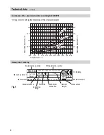
Page 8: ...o EN 60751 Temperature in C Admissible deviation in C Admissible deviation in Ω 2 1 5 1 0 5 4 3 2 1 200 100 0 100 200 300 400 500 600 700 800 Class B C Class A C Class B Ω Class A Ω TRG 5 63 0525 L 100 36 bar 251 C STW STB 117908 1230 TW 1182 1232 392938 Münchener Str 77 D 28215 Bremen GESTRA AG 1x Pt 100 Klasse A 1 4571 IP 65 G 1 2 Measuring element DIN Registration number Material number Protect...

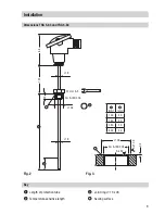
Page 9: ... 5 64 Fig 2 84 120 15 26 9 9 1 mm 2 mm 100 30 160 30 250 30 400 30 27 mm A F G A ISO 228 Fig 3 Ra 3 2 Ra 12 5 G A ISO 228 26 0 5 1 Length of protection tube 2 Temperature sensitive length Key 3 Joint ring 13 x 26 4 Sealing surface 4 4 3 27 1 2 ...

Page 10: ...5 24 65 12 5 TRG 5 68 200 30 25 24 65 12 5 Installation Dimensions TRG 5 65 TRG 5 66 TRG 5 67 and TRG 5 68 Fig 4 84 140 8 11 7 6 17 24 A F 0 Key 5 Length of welding sleeve 6 Temperature sensitive length 7 Threaded part 8 Diameter of welding sleeve 9 Cone shaped part 0 Tip of cone shaped part continued 5 9 ...

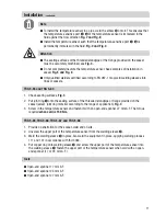
Page 11: ... seating surfaces Fig 3 2 Put joint ring 3 onto the sealing surface of the threaded standpipe or flange provided on the vessel select joint ring material according to the range of application Fig 3 3 Screw in the temperature sensor and fasten it with an open end spanner 27 mm A F The torque required when cold is 150 Nm TRG 5 65 TRG 5 66 TRG 5 67 and TRG 5 68 1 Provide a penetration for the socket ...

Page 12: ...12 Installation Examples of installation Fig 5 Fig 8 c a 100 c Fig 6 Fig 7 100 a continued b b ...

Page 13: ...5 63 TRG 5 64 TRG 5 65 TRG 5 66 TRG 5 67 and TRG 5 68 terminal box f e d Fig 9 g a Protection tube welding sleeve b Thermal insulation c Elbow d Top of terminal box e Measuring insert f Terminal box g EMC cable gland M 20 x 1 5 Key ...

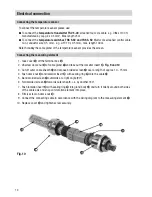
Page 14: ...ling ring i into gland body l and turn it briefly around both sides of the cable axis and snap anti rotation element into place 8 Firmly screw on dome nut h 9 Connect the connecting cable in accordance with the wiring diagram to the measuring element e 10 Replace cover d and tighten screw securely m Fig 10 h i j k l To connect the temperature sensor please use To connect the temperature transmitte...

Page 15: ...g cables leading to the equipment are segregated and run separately from power cables Wiring diagram for temperature sensor Note Additional equipment such as indicating devices can be connected to the terminals marked in yellow and black of the TRG 5 64 and TRG 5 68 Tools n Screwdriver size 2 5 completely insulated according to DIN VDE 0680 1 n Screwdriver size 8 continued Fig 11 5 3 2 6 yellow bl...

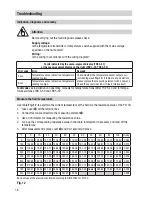
Page 16: ... for measuring the resistance value 4 Look up the corresponding resistance value in the table interpolate if necessary and read off the temperature 5 After measurement replace cover d and fix it securely in place C 0 10 20 30 40 50 60 70 80 90 100 Ω deg 0 100 00 103 90 107 79 111 67 115 54 119 40 123 24 127 07 130 89 134 70 138 50 0 385 100 138 50 142 28 146 06 149 82 153 57 157 32 161 04 164 76 1...

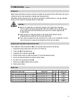
Page 17: ...terminal box 3 Disconnect the measuring element e 4 Slacken fixing screws for measuring element Pull out measuring element 5 Insert new measuring element and fasten fixing screws 6 Re attach the measuring element e 7 Replace cover d and tighten screw securely 8 Apply supply voltage Safety note Safety temperature limiters monitors are items of equipment with safety function PED and must only be ins...

Page 18: ... disposal Danger The temperature sensors TRG 5 63 or TRG 5 64 are screwed into vessels or pipes When loosening the temperature sensor steam or hot water might escape This presents the risk of severe scalding all over the body It is therefore essential not to dismantle the temperature sensor unless the boiler pressure is verified to be 0 bar The temperature sensor becomes hot during operation Risk ...

Page 19: ...19 For your Notes ...

Page 20: ...8704 05 GESTRA AG Bremen Printed in Germany GESTRA AG Münchener Straße 77 28215 Bremen Germany Telefon 49 421 3503 0 Telefax 49 421 3503 393 E mail info de gestra com Web www gestra de Agencies all over the world www gestra de ...

Reviews: