9
Installation
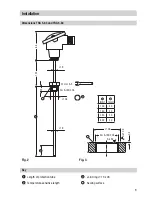
Dimensions TRG 5-63 and TRG 5-64
Fig. 2
84
120
15
∅
26
∅
9
∅
9
1
[mm]
2
[mm]
100
30
160
30
250
30
400
30
27 mm A. F.
G½ A, ISO 228
Fig. 3
Ra 3.2
Ra 12.5
G½ A, ISO 228
∅
26
0.5
1
Length of protection tube
2
Temperature-sensitive length
Key
3
Joint ring
∅
13 x 26
4
Sealing surface
4
4
3
27
1
2


