


23
Fig. 16 (Factory setting)
Fig. 17 (Example)
Fig. 18 (Factory setting: 250 kBits/s)
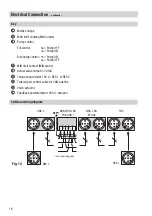
Basic Settings
– continued –
Code switch settings
8
8
Node ID
39
S1
ON
1
S2
ON
2
S3
ON
4
S4
OFF
8
S5
OFF
16
S6
ON
32
S7
OFF
64
Node ID
74
S1
OFF
1
S2
ON
2
S3
OFF
4
S4
ON
8
S5
OFF
16
S6
OFF
32
S7
ON
64
S8
S9
S0
Baud rate
Cable length
OFF
ON
OFF
250 kBit/s
125 m
ON
ON
OFF
125 kBit/s
250 m
OFF
ON
ON
100 kBit/s
335 m
ON
ON
ON
50 kBit/s
500 m
OFF
ON
ON
20 kBit/s
1000 m
ON
ON
ON
10 kBit/s
1000 m
Assigning / changing node ID
If several systems of the same kind are to communicate in one CAN bus network, be sure to assign
one node ID for each individual system component (e. g. controller, limiter). In most cases it is
sufficient to commission the equipment with the GESTRA default factory setting.
Detach the lower terminal strip
9
(Fig. 6)
in order to change the code switch
8
settings.
Attention
n
We recommend that you commission the CAN bus equipment with their GESTRA
default factory settings.
n
Make sure that no node ID is used twice in the CAN bus network!
1
ON
2 3 4 5 6 7 8 9 0
1
ON
2 3 4 5 6 7 8 9 0