17
Electrical connection
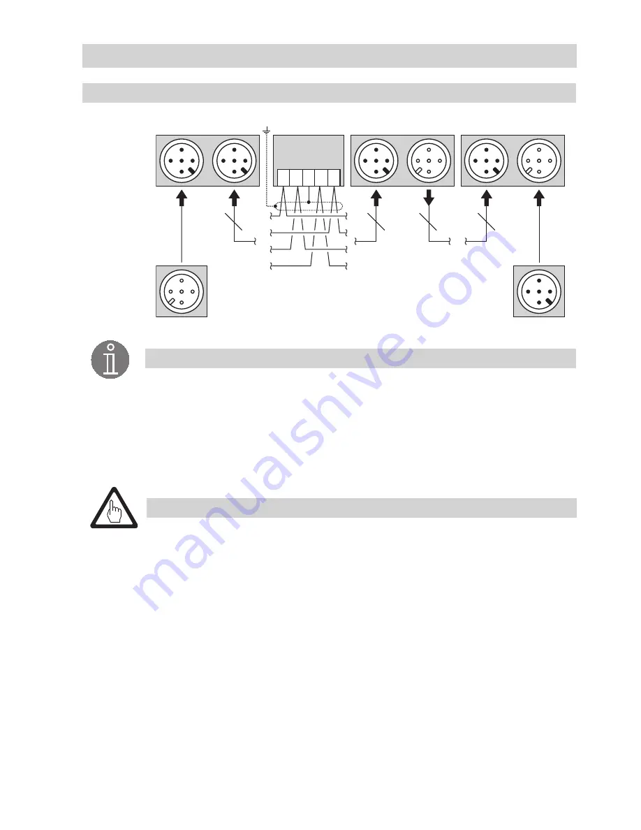
CAN bus wiring diagram
Fig. 15
+
-
C
H
C
L
S
5
5
5
5
120 Ω
120 Ω
URB 2
NRG, LRG, TRV,
EF, URZ
NRG, LRG, TRV,
EF, URZ
NRS, NRR, LRR,
TRS, URB 1
RES 2
RES 1
RES 2
CEP
NRS, NRR, LRR,
TRS, URB 1
URB 2
NRG, LRG,
EF, URZ
TRV
RES 1
Attention
Wire equipment in series. Star-type wiring is not permitted!
Link screens such that electrical continuity is ensured and connect them
once
to the
central earthing point (CEP). If equipotential bonding currents are to be expected, for
instance in outdoor installations, make sure that the screen is separated from the
central earthing point (CEP).
If two or more system components are connected in a CAN bus system, the first and
the last device must be provided with a terminating resistor of 120
Ω
!
Fig. 13, Fig. 14
Note that in a CAN bus network only
one
water-level limiting system may be used.
Do
not
interrupt the CAN bus network during operation with one or more system com-
ponents!
If the CAN bus network is interrupted the safety circuit will be opened.
Before taking the CAN bus line from the terminal strip, make sure that all connected
system components are out of service.
Note
The max. baud rates and cable lengths indicated above are based on empirical values
obtained by GESTRA. In certain cases it may be necessary to reduce the baud rate in
order to ensure operational safety.
The type of wiring has a strong influence on the electromagnetic compatibility (EMC)
of the equipment. Take special care when connecting the equipment.
If you do not use the control cable assemblies connect the connectors and jacks as
indicated in the assignment diagram for connector / jack.
- continued -


