gerkros Attack NSK Instructions For Use Manual Download Page 11

9

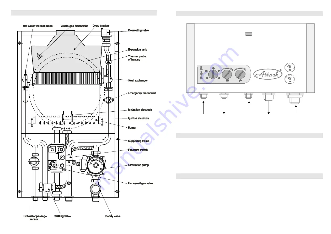
Main parts of the NSK boiler

3

Bar

D.H.W. inlet

1/2”

Gas inlet

3/4”

C.H. outlet

3/4”

C.H. inlet

3/4”

D,H.W. outlet

1/2”

10

Connecting the boiler to water and gas:

Connecting the boiler to electric net

Operation control

The boiler is plugged into the electric net socket with a supply lead with a plug. The socket
must suit to appropriate standards , various multiplugs and lenghtening cables are not

allowed to use. Installation of the socket, connecting the space thermostat and service of

electric parts of the boiler can be only performed by a person with special electric

qualification by the Public Notice No. 718/2002 Z.z. Electric installation is ready for
additional connection of room thermostat.

During the operation the boiler is secured against dangerous operation conditions.

However, the breakdowns the cause of which is not included in the boiler mechanism,

cannot be protected to arise. Therefore it is necessary after putting the boiler to operation to

examine the boiler once in three days and check:
– whether the system is filled with water and there is no discharge
– whether waste gases or gas cannot be smelled

Found breakdowns must be reported to the service worker who put the boiler to
operation. If there is a gas discharge, the gas supply must be closed. Found breakdowns

must be removed immediately.

Summary of Contents for Attack NSK

Page 1: ......

Page 2: ...ignitionandionization unit 25 Defectsofignition unit 26 The chart ofNST connecting 27 The chart ofNSK connecting pump characteristics 28 Setting minimum and maximum output 29 Notes 30 Record on putting the boilerinto operation and obligatory service inspections Putting the boiler into operation Before first putting into operation it is necessary to take following steps Procedure of the first boile...

Page 3: ...ignitionandionization unit 25 Defectsofignition unit 26 The chart ofNST connecting 27 The chart ofNSK connecting pump characteristics 28 Setting minimum and maximum output 29 Notes 30 Record on putting the boilerinto operation and obligatory service inspections Putting the boiler into operation Before first putting into operation it is necessary to take following steps Procedure of the first boile...

Page 4: ... part of the boiler accessories Connecting the boiler to the heating system is through screw joints G 3 4 Hot water as well as gas inlet is connected through screw joints G3 4 Before installing the boiler it is necessary to make surethat the chosenplace fits to requirements for waste gas escape and that minimum distances before mentioned are kept As this boiler is fast heating equipped with its ow...

Page 5: ... part of the boiler accessories Connecting the boiler to the heating system is through screw joints G 3 4 Hot water as well as gas inlet is connected through screw joints G3 4 Before installing the boiler it is necessary to make surethat the chosenplace fits to requirements for waste gas escape and that minimum distances before mentioned are kept As this boiler is fast heating equipped with its ow...

Page 6: ...necessary operating conditions whether it is an appliance with open combustion chamber flue or with closed combustion chamber turbo and with regard to the ways of combustion air supply and waste gas exhaust The service of the boiler must be carried out by the rules described in this manual Except service works the user must not carry out any repairson the appliance nor adjustments or dismounting a...

Page 7: ...necessary operating conditions whether it is an appliance with open combustion chamber flue or with closed combustion chamber turbo and with regard to the ways of combustion air supply and waste gas exhaust The service of the boiler must be carried out by the rules described in this manual Except service works the user must not carry out any repairson the appliance nor adjustments or dismounting a...

Page 8: ...7 445 700 355 183 NST Ventilator Flue 225 NSK Outside dimensions of the boiler 60 140 50 290 110 380 C H D H W D H W C H Gas 8 Mainpartsofthe NST boiler 3 Bar ...

Page 9: ...7 445 700 355 183 NST Ventilator Flue 225 NSK Outside dimensions of the boiler 60 140 50 290 110 380 C H D H W D H W C H Gas 8 Mainpartsofthe NST boiler 3 Bar ...

Page 10: ...ecial electric qualification by the Public Notice No 718 2002 Z z Electric installation is ready for additional connection ofroom thermostat During the operation theboiler is secured against dangerous operation conditions However the breakdowns the cause of which is not included in the boiler mechanism cannot beprotected to arise Therefore it is necessary after putting theboiler to operation to ex...

Page 11: ...ecial electric qualification by the Public Notice No 718 2002 Z z Electric installation is ready for additional connection ofroom thermostat During the operation theboiler is secured against dangerous operation conditions However the breakdowns the cause of which is not included in the boiler mechanism cannot beprotected to arise Therefore it is necessary after putting theboiler to operation to ex...

Page 12: ... ATTACK NST NSK boilers are delivered completely assemblied and tested functionally The delivery includes following documentation instruction for use with a document on boiler testing on the back side of the instruction letter of guarantee list of contract partners Waste gas exhaust Spare parts Guarantee reclamation Waste gas exhaust and combustion air comethrough doublepiping turbo version delive...

Page 13: ... ATTACK NST NSK boilers are delivered completely assemblied and tested functionally The delivery includes following documentation instruction for use with a document on boiler testing on the back side of the instruction letter of guarantee list of contract partners Waste gas exhaust Spare parts Guarantee reclamation Waste gas exhaust and combustion air comethrough doublepiping turbo version delive...

Page 14: ...uction for use Localization of boilersmust suit to project documentation Boilers are to be situated in the way to ensure all the operation conditions needed foran appliance with open combustion chamber flue as well as for closed combustion chamber turbo with regard to theway of combustion air supply and waste gas exhaust From the sides of boilers there must be free access of at least 0 2 m and in ...

Page 15: ...uction for use Localization of boilersmust suit to project documentation Boilers are to be situated in the way to ensure all the operation conditions needed foran appliance with open combustion chamber flue as well as for closed combustion chamber turbo with regard to theway of combustion air supply and waste gas exhaust From the sides of boilers there must be free access of at least 0 2 m and in ...

Page 16: ...ating system Connecting to water piping Connecting boilers to gas pipeline ATTACK boilers serve for heating systems with forced circulation Rate of waterflow can be set by the switch on the pump Before filling the heating system with water it is necessary to clean the system properly Heaters and distribution must be washed several times For thorough washing and cleaning the heating system we recom...

Page 17: ...ating system Connecting to water piping Connecting boilers to gas pipeline ATTACK boilers serve for heating systems with forced circulation Rate of waterflow can be set by the switch on the pump Before filling the heating system with water it is necessary to clean the system properly Heaters and distribution must be washed several times For thorough washing and cleaning the heating system we recom...

Page 18: ...in After opening hot water the circulationpump of the heating circuit stops Starting output set up by resistance trimer P5 is kept after burning theboiler in the time of two seconds Then the boileroutput is controlled by PID regulation by the passage and temperature of hot water to reach the set temperature as soon as possible When the waterpassage drops under 2 5 l min the operation phase of hot ...

Page 19: ...in After opening hot water the circulationpump of the heating circuit stops Starting output set up by resistance trimer P5 is kept after burning theboiler in the time of two seconds Then the boileroutput is controlled by PID regulation by the passage and temperature of hot water to reach the set temperature as soon as possible When the waterpassage drops under 2 5 l min the operation phase of hot ...

Page 20: ... out and a failure is signalled Reignition is not possible for 30 minutes This time period can be cleared reset with the operation switch If this function is chosen the boiler starts working in the heating mode to the maximum output of the burner and maximum temperature of the heating water 80 C The burner is off after reaching the maximum switch off temperature 85 C If there is a request for hot ...

Page 21: ... out and a failure is signalled Reignition is not possible for 30 minutes This time period can be cleared reset with the operation switch If this function is chosen the boiler starts working in the heating mode to the maximum output of the burner and maximum temperature of the heating water 80 C The burner is off after reaching the maximum switch off temperature 85 C If there is a request for hot ...

Page 22: ... 1 02 1 00 0 97 Resistance Temperature Resistance Temperature Resistance Temperature x B 1 1 T T10 230 V 10 15 2AF 250VAC 10 m 230 V0 1A MAX cos 0 4 230 V0 4A MAX cos 0 4 230 V0 35A MAX cos 0 4 20 C 60 C 35 60 C 70 C 30 C 80 C 20 C 40 C 35 C 85 C 25 C 75 C 10 K 0 alebo 180 sek 6 C 25 C 2 sek 45 220 mA 7 5 65 310 mA 7 5 0 80 I max 0 100 I max 10 k 1 3435 1 10 m A500 VDC R R T TO x e 21 Technical pa...

Page 23: ... 1 02 1 00 0 97 Resistance Temperature Resistance Temperature Resistance Temperature x B 1 1 T T10 230 V 10 15 2AF 250VAC 10 m 230 V0 1A MAX cos 0 4 230 V0 4A MAX cos 0 4 230 V0 35A MAX cos 0 4 20 C 60 C 35 60 C 70 C 30 C 80 C 20 C 40 C 35 C 85 C 25 C 75 C 10 K 0 alebo 180 sek 6 C 25 C 2 sek 45 220 mA 7 5 65 310 mA 7 5 0 80 I max 0 100 I max 10 k 1 3435 1 10 m A500 VDC R R T TO x e 21 Technical pa...

Page 24: ...ion of the burner by discharge spark and monitoring presenceof flame with ionization electrode Technical parameters Flame detection The circuit measuring amplifier sensitivity Table of values 230V 50 Hz Ignition Working programm and times Basic functional characteristics Minimum ionization current Maximum length of ionization cable Maximum parasitic capacity Minimum resistance of ionization electr...

Page 25: ...ion of the burner by discharge spark and monitoring presenceof flame with ionization electrode Technical parameters Flame detection The circuit measuring amplifier sensitivity Table of values 230V 50 Hz Ignition Working programm and times Basic functional characteristics Minimum ionization current Maximum length of ionization cable Maximum parasitic capacity Minimum resistance of ionization electr...

Page 26: ...ped Repeated cycling in the case of flame failure during operation The failure that can be remedied by switching off and on the main supply of power if the flame is not present Note Note If CMF unit finds flame simulation it reports anomaly and if this situation lasts longer than 15 seconds the request for heat is stopped it is switched off by a relay A new try for ignition can occur only after re...

Page 27: ...ped Repeated cycling in the case of flame failure during operation The failure that can be remedied by switching off and on the main supply of power if the flame is not present Note Note If CMF unit finds flame simulation it reports anomaly and if this situation lasts longer than 15 seconds the request for heat is stopped it is switched off by a relay A new try for ignition can occur only after re...

Page 28: ... in the probe for measuring inlet gas pressure connect manometer and read the measured value 2mbar Screwin the bolt in the probe for measuring inlet gas pressure release thebolt in the probe for measuring gas pressure on burner nozzles connect manometer and read the measured value by the chart of pressure setting in the case of setting minimum and maximum pressure on nozzles following actions are ...

Page 29: ... in the probe for measuring inlet gas pressure connect manometer and read the measured value 2mbar Screwin the bolt in the probe for measuring inlet gas pressure release thebolt in the probe for measuring gas pressure on burner nozzles connect manometer and read the measured value by the chart of pressure setting in the case of setting minimum and maximum pressure on nozzles following actions are ...

Page 30: ...o operation Service company Stamp signature Obligatory service examination after the 3rd year of operation Date Stamp signature Obligatory service examination after the 1st year of operation Date Stamp signature Obligatory service examination after the 2nd year of operation Date Stamp signature 29 Notes ...

Page 31: ...o operation Service company Stamp signature Obligatory service examination after the 3rd year of operation Date Stamp signature Obligatory service examination after the 1st year of operation Date Stamp signature Obligatory service examination after the 2nd year of operation Date Stamp signature 29 Notes ...

Page 32: ...LOVAKIA DOCUMENT on testing and completness of ATTACK gas boiler Boiler production No The product delivered with this certificate suits to technical standards and technical conditions The product was manufactured by its drawing design in requested quality and is approved by TECHNICAL TESTING FACILITY SKTC104 in Piešťany under the No of certificate 00846 104 2 2002 00847 104 2 2002 Technical inspec...

Reviews: