background image

Offline Operation

Downloading Firmware 

4-23

Downloading Firmware

Downloading Firmware

The firmware is a set of instructions which determines how the plotter will

respond to the commands you choose from the menus and those it receives

from the grading and marking system. Firmware is permanently stored in the

control circuitry of the plotter. The Download function allows you to

incorporate new versions.

NOTE:

NOTE:

When updating firmware, be sure to read all instructions and release notes

supplied with the new firmware, before beginning, as there may be

parameters that you have to record.

Downloading new firmware requires you to perform steps both from the

plotter control panel and from the host system (the system physically

connected to the plotter).
From the plotter control panel you get the plotter ready to receive new

firmware. Also, after the programs have been successfully transferred, the

control panel provides the menu command to permanently load the new

programs into the plotter.
The commands for transferring the programs are entered at the host system

keyboard. The status of the update process appears on the plotter control

panel display, as well as any error messages.

Summary of Contents for AccuPlot AP-100

Page 1: ...AccuPlot AP 100 AP 300 AP 520 USER S GUIDE...

Page 2: ...0 1 1 2 3 3 4 3 4 3 4 4 3 3 3 5 3 0 6 7 5 8 7 9 8 7 9 6 1...

Page 3: ...ers 2 STARTING AND STOPPING THE PLOTTERS CHAPTER 2 Power On and Initialization 1 Power On 1 Initializing the Plotter 2 Putting the Plotter Online 3 Stopping the Plotter 4 Offline 4 Power Down 4 PLOTTE...

Page 4: ...AP 300 9 Switching to the Second Paper Roll 12 Using Paper Width Adapters 13 Plotter Pen Maintenance 14 Task overview 14 AJ 520 Pen Maintenance 15 AccuPlot Longlife Pen Maintenance 18 GLOSSARY G 1 IND...

Page 5: ...organized into the following chapters 1 Introduction This chapter covers AccuPlot and AccuJet safety procedures 2 Starting and Stopping Plotters This chapter describes how to turn on and turn off the...

Page 6: ...and the steps have all necessary tools or supplies and are aware of any warnings GGT Product Support As part of our commitment to excellence GGT provides complete worldwide support for the AccuJet and...

Page 7: ...300 use a different paper transport method and a smaller diameter paper roll than the other plotter models The only difference between the AP 320 and AP 360 models is the maximum paper width that can...

Page 8: ...e path of the beam at all times Do not perform any maintenance on the plotter while the servos are enabled Do not access the electrical panels while power is applied Emergency Stop Emergency Stop The...

Page 9: ...been turned off or after an Emergency Stop E Stop is detected Initializing clears the system s memory buffer and positions the head at the origin starting position NOTE Before turning the system on be...

Page 10: ...the operating parameters currently defined for the plotter You must initialize the plotter after turning the power on and after any emergency stop TO INITIALIZE THE PLOTTER 1 From page one of the Off...

Page 11: ...ING FAILURE TO KEEP HANDS AND CLOTHING AWAY FROM THE PLOTTING AREA WHEN THE PLOTTER IS ONLINE MAY RESULT IN INJURY On a network jobs can be sent to the plotter from any system on the network Do not as...

Page 12: ...obs in process is retained If however you turn the plotter power off while it is plotting plot data is lost Offline TO TAKE THE PLOTTER OFFLINE 1 From the ONLINE display press F3 OFFLINE NOTE Do not m...

Page 13: ...Take up AP 100 disposable 1550 mm 61 0 in 165 mm 6 5 in no whip 915 x 2090 mm 36 x 83 in no AP 110 disposable 1550 mm 61 0 in 241mm 9 5 in yes whip 915 x 2090 mm 36 x 83 in no AP 300 disposable 2000 m...

Page 14: ...ary Note Note All locations assume that you are standing at and facing the control panel Figure 3 1 Top view of the AP 320 Paper Take up Roll Drive Roller Pinch Roller Carriage Pen Assembly Supply Rol...

Page 15: ...Roller with independent Grippers Carriage Assembly contains the Long Life Pen and the Inkjet Assemblies Control Panel with Emergency Stop Switch Power on off switch located just above paper supply ro...

Page 16: ...off switch and data connectors Figures 3 3 and 3 4 show the power panels for the AccuPlot and the AccuJet plotters Line Power Main Power Switch Computer Far end of the paper roll Figure 3 3 AccuPlot...

Page 17: ...d AP 300 include a PINCH ROLLER which holds the paper onto the drive roller during page advances On the AccuJet 520 individual GRIPPERS perform the same function The pinch roller grippers must be in c...

Page 18: ...The control panel design shown in Figure 3 6 is the same for both families of plotters F1 F2 F3 F4 1 2 Arrow Keys Function Keys F1 F4 Menu Key Enter Key Display Window Emergency Stop Figure 3 6 Contro...

Page 19: ...s pressed Function Keys To choose from a menu or to respond to a prompt press the function key associated with your choice or response F1 F2 F3 F4 Lines indicate which function key controls which opti...

Page 20: ...ientation Table Orientation Some procedures in this guide refer to the X axis the Y axis or the origin point Figure 3 7 shows each axis direction and the GGT default origin Figure 3 7 X axis Y axis an...

Page 21: ...ee sections called PAGES Press the menu key to move from page to page Page One options allow you to initialize the plotter put the plotter online adjust the paper position or move the pen origin Page...

Page 22: ...2 Offline Menu Page 3 DIAGNOSTICS SERVICE EXIT DIAG PLOTS DISPLAY DIAG IO DIAGS SERVO DIAGS TOOL up down PARAM ENTRY SERVO DIS TOOL TMR OFFLINE DOWNLOAD DIAGNOSTICS PAGE 2 SERVO MISC INKJET PEN DIAG...

Page 23: ...for the plotter and moves the paper forward about 13 mm inch TO INITIALIZE THE PLOTTER 1 From page one of the the Offline menu press F2 INITIALIZE To stop initializing press F3 STOP Putting the Plotte...

Page 24: ...th is 406 mm 16 25 inches Window length is adjustable in 17mm 0 68 inch increments in order to limit the space between adjoining markers TO ADVANCE THE PAPER 1 From page one of the Offline menu press...

Page 25: ...rom the Offline menu to display the Paper Advance menu 3 Press F3 REVERSE The paper automatically reverses The message Reversing Paper displays briefly then the Paper Advance screen reappears 4 Using...

Page 26: ...nently change the origin use Param Entry menu commands see Changing Parameters page 4 12 TO SET A TEMPORARY ORIGIN 1 Press F4 ORIGIN from the Offline menu 2 When the current pen position displays use...

Page 27: ...splays Tool Down If the pen is lowered the menu displays Tool Up TO LOWER OR RAISE THE PEN 1 From page one of the Offline menu press the Menu key one time to display page two 2 From page two press F1...

Page 28: ...ASK THAT REQUIRES PUTTING YOUR HANDS NEAR THE PLOTTING AREA FAILURE TO DISABLE SERVOS MAY RESULT IN INJURY TO DISABLE SERVOS 1 From page one of the Offline menu press the Menu key one time to display...

Page 29: ...E PLOTTING AREA MAY RESULT IN INJURY TO ENABLE SERVOS 1 Verify that the plotting area is clear and that the sliding covers are closed 2 From the Servo Disable menu press F2 RESUME 3 Press the Enter ke...

Page 30: ...bling Servo Power Resetting the Plotter TO RESET THE PLOTTER 1 From the Servo Disable menu press F3 RESET The plotter resets and displays the message Press Enter to Enable the Plotter on the control p...

Page 31: ...lt values are reloaded the next time you initialize the plotter Saved parameter settings remain as you set them even when the plotter is powered off You can also reload the GGT default parameters if n...

Page 32: ...line menu press F2 PARAM ENTRY to display page one of the Parameter Entry menu 3 Press F1 CHG PARAM to display page one of the Change Parameter menu From this menu you can change Table Plot and Paper...

Page 33: ...Press F3 SIGN to change a positive value to negative or a negative value to positive 4 When you have completed your changes press the Enter key to record the new value NOTE You must press Enter to rec...

Page 34: ...default X axis origin position AJ 520 00 17 inches AP 100 300 320 360 00 00 inches Y Origin Position Sets default Y axis origin position 00 00 inches X Table Size Sets default X axis table dimension...

Page 35: ...Y axis AJ 520 2 0 Gs AP 100 300 320 360 2 5 Gs Annotation Acceleration Sets acceleration rate of characters being drawn when using pen for annotation AJ 520 2 0 Gs AP 100 300 320 360 2 5 Gs Annotatio...

Page 36: ...the internal controls the plotter uses for paper movement and should not be adjusted TABLE 4 3 ACCUJET PAPER ADVANCE PARAMETERS parameter function default Flat PWM Command Used for development or fie...

Page 37: ...parameter function default Language Sets menu language from standard to alternate 0 standard 1 alternate 0 STD Font Type Sets style of font used in plotting 0 fast 1 elaborate 0 FST Character Set Sets...

Page 38: ...her value makes a darker annotation 1 strike s Offset Test DIM A Used for development or field service 0 inches Offset Test DIM B Used for development or field service 0 inches Offset Test DIM C Used...

Page 39: ...press the Menu key one time to display page two 2 From page two of the Offline menu press F2 Param Entry to display page one of the Parameter Entry menu 3 Press F3 Save Param The message Storing Param...

Page 40: ...s use the Change Parameter option TO LOAD THE DEFAULT PARAMETERS 1 From the Param Entry menu press F2 Load Default The message Loading Defaults appears in the display window until the process is compl...

Page 41: ...ter entry screen the plotter automatically stops when the distance expires TO SET THE PEN TIMER 1 From page one of the Offline menu press the Menu key one time to display page two 2 From page two of t...

Page 42: ...r menu 3 Press F2 Inkjet Timer to see the current values 4 Do one of the following Press F1 New Cartridge to restart the timer after installing a new inkjet cartridge Press F2 Timer On to enable the t...

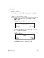
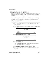
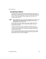
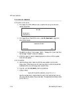
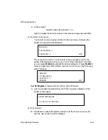
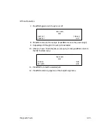
Page 43: ...pplied with the new firmware before beginning as there may be parameters that you have to record Downloading new firmware requires you to perform steps both from the plotter control panel and from the...

Page 44: ...essage appears continue with the update from the host system at the host system 5 Insert the floppy disk containing the firmware update into the host s floppy drive If the floppy drive is not active t...

Page 45: ...an error screen displays From there you can press F2 Retry to attempt the download again or press F4 Exit to return to page three of the Offline menu If no errors occur the following screen displays P...

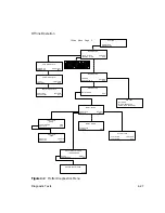
Page 46: ...pecific settings Diagnostic Tests Diagnostic Tests Diagnostic menu commands allow you test the operation capability of plotter components Most of these diagnostics are used primarily by service person...

Page 47: ...FONT TEST OFFSET TEST MULTI DIR EXIT FONT TEST EXIT DIAGNOSTICS IO DIAGS SERVO DIAGS SERVICE EXIT INKJET DIAGS TEST JETS ROTATE OFFSET EXIT ROTATE INKJET HEAD DEGREES START CONTINUOUS SIGN EXIT ROTAT...

Page 48: ...F2 Display Diag to test the control panel display screen page 4 32 Press F3 Key Diag to test control panel keys page 4 33 Press the Menu key to display page two below This menu allows you to check co...

Page 49: ...page three you can test Inkjets TO DISPLAY DIAGNOSTIC PLOTS MENUS 1 From page one of the Diagnostics menu press F1 Diag Plots to display page one of the Diag Plots menu pen plots 2 Press the menu key...

Page 50: ...to display the Diag Plot page that lists the test you want 3 Press the function key associated with the test you want to perform A screen similar to the one shown below displays when you choose a tes...

Page 51: ...plotter accuracy and beam squareness The diagonals should be equal in length and all sides of the box should measure within 1 32 inch Life test Intended for GGT Field Service use The Life test draws...

Page 52: ...lluminate for approximately five seconds TO RUN THE DISPLAY DIAG TEST 1 From page three of the Offline menu press F2 Diagnostics to display page one of the Diagnostics menu 2 Press F2 Display Diag The...

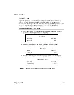
Page 53: ...name of the key appears in the screen 4 To exit this test press the Enter key then the Menu key Inkjet Diagnostics The Inkjet assembly contains two banks of jets Each bank contains 25 jets There are...

Page 54: ...ts NOTE NOTE When you press F1 the menu item changes to show the bank not currently chosen 5 Press F3 Fire to test the entire bank Verify the plotter draws a vertical line 6 Press F2 Set Jets to selec...

Page 55: ...evious jet 9 Repeat steps 6 through 8 for each jet to be tested 10 After you have chosen the jets you are going to test press F4 to return to the first Test Jets menu 11 Press F3 Fire to test the sele...

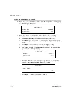
Page 56: ...e current rotation appears below the menu title 5 Press the F3 key to select a positive or negative rotation 6 Do one of the following Press F1 Start to rotate the head to the selected angle Press F2...

Page 57: ...only by qualified service personnel Plotter Supplies Plotter Supplies Plotter supplies are available directly from GGT Table 5 1 lists supplies and their part numbers To place an order call GGT s toll...

Page 58: ...Inspect and clean the AccuPlot pen cartridge using the procedure on page 5 18 Weekly Clean the beam and linear bearing by wiping them with alcohol on a lint free cloth Lubricate the linear bearing wi...

Page 59: ...tube must be the same length as the supply roll If you are replacing an empty supply roll you can use that as the new take up roll Masking tape Loading paper requires that you load the new supply rol...

Page 60: ...the right This depresses the spring loaded hub at the far end of the plotter and frees the near end from the drive hub Lift the bar away from the plotter and lay it on the floor 3 Using a inch hex wre...

Page 61: ...all the supply roll Lift the supply roll bar up and insert the right end of the supply roll bar into the spring loaded hub Shift the bar toward the right until your helper can insert the left end into...

Page 62: ...supply roll to lower the dancer bar in the pocket until it lines up with the holders at both ends of the bar Connect one side of the dancer bar by inserting the pin at the end of the bar into the hol...

Page 63: ...end of the take up roll bar 3 Remove the take up roll bar from the plotter and lay it on the floor Remove the plastic end plate from the far end by using a inch hex wrench to loosen the screw on the...

Page 64: ...l bar to take up any slack Lower the paper grips 8 Restart the plotter and advance the paper Make sure the sliding covers are closed Also check that the carriage is not all the way to either end of th...

Page 65: ...grasp the empty supply roll and shift it to your right This depresses the spring loaded hub at the far end of the plotter and frees the closer end of the paper roll bar from the drive hub Lift the ba...

Page 66: ...drive plug assembly engages with the drive hub pins 8 Feed the paper through the paper path Fold the end of the plotter paper to form a point Insert the point of the paper under the beam and across t...

Page 67: ...the hex wrench to loosen the drive plug in the near end of the roll Remove the plug and set it aside 14 Put the take up drive plug into the end of the empty cardboard tube and insert the roll bar 15 I...

Page 68: ...turn the take up roll to pull the paper across the table 2 Pull the free end of the paper from the second paper supply roll around the main supply roll 3 Feed the paper under the beam and across the t...

Page 69: ...ake up roll TO INSTALL PAPER WIDTH ADAPTERS 1 Slide the adapter onto the supply roll bar and adjust it so that the larger diameter is flush with the edge of the paper roll Secure the supply roll adapt...

Page 70: ...owing equipment to perform basic pen maintenance A clean soft cloth Ink Replacement pens or inkjet cartridges Pipe cleaner Pump or syringe to pressurize pen assemblies Refilling either of the long lif...

Page 71: ...RY ink reservoir fill cap ink supply tube pen Figure 5 1 AJ 520 Longlife Pen Assembly TO REPLACE THE AJ 520 LONGLIFE PEN 1 Turn Servo Power off 2 Open a sliding cover so that you can reach the carriag...

Page 72: ...ntaminants into the reservoir 3 Fill to about 10 mm from top Do not cover the top of the small tube inside the well Use a towel or cloth to prevent ink from dripping as you remove the supply bottle fr...

Page 73: ...irection of the arrow on top of the cartridge until it snaps into place in an upright position TO REPLACE THE INKJET CARTRIDGE WARNING FAILURE TO DISABLE SERVO POWER BEFORE PUTTING YOUR HANDS IN OR NE...

Page 74: ...quarter turn counterclockwise 3 Lift the pen and ink assembly out of the pen holder An AccuPlot Longlife Pen kit is available from GGT This kit includes three pen cartridge ink reservoir assemblies a...

Page 75: ...unger from the reservoir can cause a loss of pressure in the pen assembly 4 With the plunger still braced against the surface disconnect the ink reservoir from the syringe The ink will continue to fil...

Page 76: ...nsert the ink reservoir into the large round opening in the cover Line up the guide on the side of the ink reservoir with the notch in the large round opening 3 Hold the beam assembly to keep it from...

Page 77: ...marker It can be the marker or piece name size or the date and so on Arrow Key Four keys up down left and right on the control panel that allow you to move the beam and carriage over the table and to...

Page 78: ...f you need to Diagnostics A group of tests that can be run to determine if the plotter is functioning correctly You can run some of the diagnostic tests yourself but others are intended for GGT Field...

Page 79: ...lear the plotter s controls and reset the pen to the defined origin This is done each time you power up the plotter and when you want to permanently save changes to parameters Inkjet Assembly The devi...

Page 80: ...em Be careful when you put the plotter online because if you have already sent data to the plotter it will immediately begin to plot Operator Messages Messages that appear in the display window tellin...

Page 81: ...Plot File The file that contains the plotting information sent from the marking and grading system to the Plotter Once the plotter is initialized this data is plotted Power Up Power Down To turn the...

Page 82: ...ate of speed at which an object moves expressed in inches per second ips Velocity parameters can be set for plotting annotation and paper advancing Window Size The length and width that can be plotted...

Page 83: ...keys 3 6 3 7 display window 3 6 3 7 emergency stop 3 6 function keys 3 6 3 7 menu key 3 6 3 7 Covers 1 2 D D Dancer Bar 3 5 5 6 Default Parameters See Parameters Description Plotters 3 1 Diagnostics...

Page 84: ...pen overview 5 15 AJ 520 pen refill 5 16 AJ 520 pen replacement 5 15 AP 100 pen installation 5 20 AP 100 pen overview 5 18 AP 100 pen pressurize 5 19 AP 100 pen removal 5 18 AP 300 pen installation 5...

Page 85: ...17 plot acceleration 4 15 plot velocity 4 15 plot 4 15 rev flat PWM command 4 16 rev ramp down period 4 16 rev ramp up period 4 16 save 4 19 table 4 14 view current settings 4 13 X jet 1 offset 4 18 X...

Page 86: ...Supplies 5 1 Supply Roll See Paper Support iv T T Table orientation 3 8 parameters 4 14 Take up Roll reversing 4 5 See also Paper Technical Support iv Tests See Diagnostic Timers inkjet See Inkjet pen...

Page 87: ...ERNATIONAL INTERNATIONAL INTERNATIONAL INTERNATIONAL Gerber Technology Inc INTERNATIONAL DIVISION P O Box 769 24 Industrial Park Road West Tolland Connecticut 06084 USA TEL 860 871 8082 WEB http www g...

Reviews: