


5
1.4 Overview
1
11
2
3
4
5
6
8
10
9
12
7
13
14
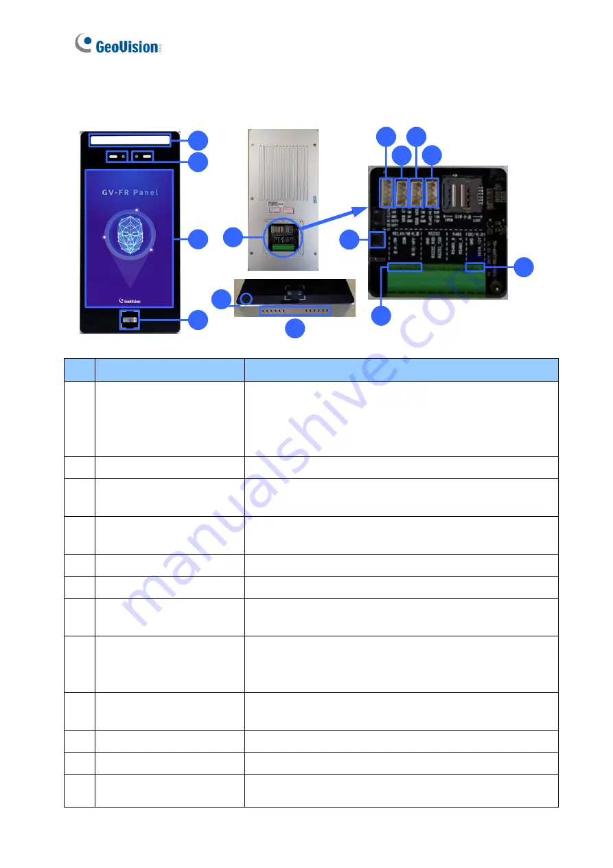
No. Name
Function
1
LED Light
•
White LED: Turns on LED lighting when its radar sensor
detects motion.
•
Green LED: Turns on when recognizing registered faces.
•
Red LED Turns on when detecting unknown faces.
2
Built-in Cameras
Captures real-time live images at the front of the panel.
3
Touchscreen Panel
Displays the live images captured by the built-in cameras
and accesses its local settings.
4
QR Code Reader
Reads QR codes used for access control. The QR code LED
turns on when detecting motion around.
5
Rear Panel
Contains all the ports of the GV-FR Panel, see No. 6
– 10.
6
Reset Button
Restarts the GV-FR Panel.
7
Wiegand Port
Connects to 3
rd
-party controllers. See
Chapter 7 Third-Party
Controller
Integration
.
8
USB OTG PH2.0-4P Port
Connects to a PC for data backup and/or firmware upgrade
via the supplied USB OTG PH2.0-4P cable
(currently non-functional).
9
USB Host PH2.0-4P Port
Connects to a USB keyboard or mouse via the supplied USB
Host PH2.0-4P cable.
10
RJ-45 Port
Connects to the network via the supplied RJ-45 cable.
11
Relay Output
Contains the following 3 relay pins: NO, COM and NC.
12
2-Pin Power connector
Connects to power via the supplied 2-pin power cable and an
optional power adapter.


