


10
ECO-Y INSTALLATION MANUAL
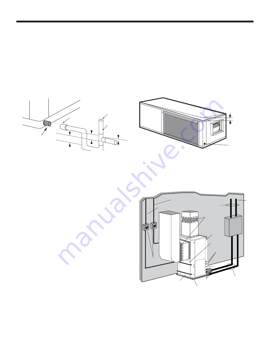
1/2'' Pitch
Drain
Unit Pitch for Drain
Horizontal Drain Connection (Composite Drain Pan)
Condensate Drain
On vertical units, the internal condensate drain assembly consists
of a drain tube which is connected to the drain pan, a 3/4 in. PVC
female adapter and a flexible connecting hose. The female adapter
may exit either the front or the side of the cabinet. The adapter
should be glued to the field-installed PVC condensate piping.
On vertical units, a condensate hose is inside all cabinets as a
trapping loop; therefore, an external trap is not necessary.
On horizontal units, a PVC stub is provided for condensate drain
piping connection. An external trap is required (see below). If a
vent is necessary, an open stand pipe may be applied to a tee in
the field-installed condensate piping.
1.5"
1.5"
3/4” PVC tube stub
3/4" PVC
Coupling
Vent (if needed)
3/4" PVC
1/8" per foot
NOTE:
For closed loop systems with antifreeze protection, set
SW1-2 to the “loop” position.
Once piping is completed between the unit, pumps and the ground
loop, final purging and charging of the loop is required. A flush
cart (or a 1.5 HP pump minimum) is needed to achieve adequate
flow velocity in the loop to purge air and dirt particles from the
loop itself. Antifreeze solution is used in most areas to prevent
freezing. Flush the system adequately to remove as much air as
possible then pressurize the loop to a static pressure of 40-50
PSI (summer) or 50-75 PSI (winter). This is normally adequate
for good system operation. Loop static pressure will fluctuate with
the seasons. Pressures will be higher in the winter months than
during the cooling season. This fluctuation is normal and should be
considered when initially charging the system.
After pressurization, be sure to turn the venting (burping) screw in
the center of the pump two (2) turns open (water will drip out), wait
until all air is purged from the pump, then tighten the plug. Ensure
that the loop pumps provide adequate flow through the unit(s)
by checking the pressure drop across the heat exchanger and
comparing it to the unit capacity data in the specification catalog.
2.5 to 3 GPM of flow per ton of cooling capacity is recommended in
earth loop applications.
Closed Loop Ground Source Systems
Closed Loop Ground Source Application
Flexible Duct
Collar
Vibration Absorbing Pad
P/T Plugs
Drain
Hot Water Generator
Connections
Auxiliary
Heater
Knockout
Low
Voltage to
Thermostat
Unit Supply
Auxiliary Heat
Supply
Insulated piping
or hose kit
Disconnects
(If Applicable)
Unit Power
P/T
TO
LOOP
GeoLin
k
®
Flow
Center
GeoLink
®
Polyethylene w/
Armaflex
®
Insulation
NOTE:
Additional information can be found in Flow Center
installation manual and Flush Cart manual.