background image

22 

APPENDIX A. THERMISTOR TEMPERATURE DERIVATION 

 
Thermistor Type: YSI 44005, Dale #1C3001-B3, Alpha #13A3001-B3 
Resistance to Temperature Equation: 
 

T=

1

A+B

(

LnR

)

+C(LnR)

3

-273.2 


Equation 5 - Resistance to Temperature 

Where; 


=

 Temperature in 

°

C. 

LnR 

=

 Natural Log of Thermistor Resistance. 

=

 1.4051 

×

 10-3 

=

 2.369 

×

 10-4 

=

 1.019 

×

 10-7 

Note: Coefficients calculated over the 

50 to +150

°

 C. span. 

Ohms 

Temp 

Ohms 

Temp 

Ohms 

Temp 

Ohms 

Temp 

Ohms 

Temp  

201.1K 

-50 

16.60K 

-10 

2417 

+

30 

525.4 

+

70 

153.2 

+

110 

187.3K 

-49 

15.72K 

-9 

2317 

31 

507.8 

71 

149.0 

111 

174.5K 

-48 

14.90K 

-8 

2221 

32 

490.9 

72 

145.0 

112 

162.7K 

-47 

14.12K 

-7 

2130 

33 

474.7 

73 

141.1 

113 

151.7K 

-46 

13.39K 

-6 

2042 

34 

459.0 

74 

137.2 

114 

141.6K 

-45 

12.70K 

-5 

1959 

35 

444.0 

75 

133.6 

115 

132.2K 

-44 

12.05K 

-4 

1880 

36 

429.5 

76 

130.0 

116 

123.5K 

-43 

11.44K 

-3 

1805 

37 

415.6 

77 

126.5 

117 

115.4K 

-42 

10.86K 

-2 

1733 

38 

402.2 

78 

123.2 

118 

107.9K 

-41 

10.31K 

-1 

1664 

39 

389.3 

79 

119.9 

119 

101.0K 

-40 

9796 

1598 

40 

376.9 

80 

116.8 

120 

94.48K 

-39 

9310 

+

1535 

41 

364.9 

81 

113.8 

121 

88.46K 

-38 

8851 

1475 

42 

353.4 

82 

110.8 

122 

82.87K 

-37 

8417 

1418 

43 

342.2 

83 

107.9 

123 

77.66K 

-36 

8006 

1363 

44 

331.5 

84 

105.2 

124 

72.81K 

-35 

7618 

1310 

45 

321.2 

85 

102.5 

125 

68.30K 

-34 

7252 

1260 

46 

311.3 

86 

99.9 

126 

64.09K 

-33 

6905 

1212 

47 

301.7 

87 

97.3 

127 

60.17K 

-32 

6576 

1167 

48 

292.4 

88 

94.9 

128 

56.51K 

-31 

6265 

1123 

49 

283.5 

89 

92.5 

129 

53.10K 

-30 

5971 

10 

1081 

50 

274.9 

90 

90.2 

130 

49.91K 

-29 

5692 

11 

1040 

51 

266.6 

91 

87.9 

131 

46.94K 

-28 

5427 

12 

1002 

52 

258.6 

92 

85.7 

132 

44.16K 

-27 

5177 

13 

965.0 

53 

250.9 

93 

83.6 

133 

41.56K 

-26 

4939 

14 

929.6 

54 

243.4 

94 

81.6 

134 

39.13K 

-25 

4714 

15 

895.8 

55 

236.2 

95 

79.6 

135 

36.86K 

-24 

4500 

16 

863.3 

56 

229.3 

96 

77.6 

136 

34.73K 

-23 

4297 

17 

832.2 

57 

222.6 

97 

75.8 

137 

32.74K 

-22 

4105 

18 

802.3 

58 

216.1 

98 

73.9 

138 

30.87K 

-21 

3922 

19 

773.7 

59 

209.8 

99 

72.2 

139 

29.13K 

-20 

3748 

20 

746.3 

60 

203.8 

100 

70.4 

140 

27.49K 

-19 

3583 

21 

719.9 

61 

197.9 

101 

68.8 

141 

25.95K 

-18 

3426 

22 

694.7 

62 

192.2 

102 

67.1 

142 

24.51K 

-17 

3277 

23 

670.4 

63 

186.8 

103 

65.5 

143 

23.16K 

-16 

3135 

24 

647.1 

64 

181.5 

104 

64.0 

144 

21.89K 

-15 

3000 

25 

624.7 

65 

176.4 

105 

62.5 

145 

20.70K 

-14 

2872 

26 

603.3 

66 

171.4 

106 

61.1 

146 

19.58K 

-13 

2750 

27 

582.6 

67 

166.7 

107 

59.6 

147 

18.52K 

-12 

2633 

28 

562.8 

68 

162.0 

108 

58.3 

148 

17.53K 

-11 

2523 

29 

543.7 

69 

157.6 

109 

56.8 

149 


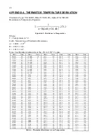
Table 6 - Thermistor Resistance versus Temperature


55.6


150 


Summary of Contents for 4450

Page 1: ...s without the written consent of Geokon Inc The information contained herein is believed to be accurate and reliable However Geokon Inc assumes no responsibility for errors omissions or misinterpretation The information herein is subject to change without notification Copyright 1994 2017 by Geokon Inc Doc Rev P 11 27 2017 ...

Page 2: ......

Page 3: ...re are no warranties except as stated herein There are no other warranties expressed or implied including but not limited to the implied warranties of merchantability and of fitness for a particular purpose Geokon Inc is not responsible for any damages or losses caused to other equipment whether direct indirect incidental special or consequential which the purchaser may experience as a result of t...

Page 4: ......

Page 5: ... 2 Sensors with Bare Leads 14 3 2 3 Operating the GK 405 14 3 3 GK 403 READOUT BOX OBSOLETE MODEL 15 3 3 1 Connecting Sensors with 10 pin Bulkhead Connectors Attached 15 3 3 2 Connecting Sensors with Bare Leads 15 3 3 3 Operating the GK 403 15 3 4 MEASURING TEMPERATURES 15 4 DATA REDUCTION 16 4 1 DEFORMATION CALCULATION 16 4 2 TEMPERATURE CORRECTION 17 4 3 ENVIRONMENTAL FACTORS 18 5 TROUBLESHOOTIN...

Page 6: ...S RANGES OF 50 MM 2 AND BELOW 24 FIGURE 13 DIMENSIONS RANGES OF 100 MM 4 AND ABOVE 25 TABLES TABLE 1 MODEL 4450 READING VERSUS POSITION IN THE RANGE 8 TABLE 2 ENGINEERING UNITS CONVERSION MULTIPLIERS 16 TABLE 3 THERMAL COEFFICIENT CALCULATION CONSTANTS 17 TABLE 4 SAMPLE RESISTANCE 21 TABLE 5 RESISTANCE WORK SHEET 21 TABLE 6 THERMISTOR RESISTANCE VERSUS TEMPERATURE 22 TABLE 7 MODEL 4450 DISPLACEMEN...

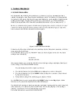
Page 7: ...rom Geokon Figure 1 Model 4450 Displacement Transducer 2 INSTALLATION 2 1 Preliminary Tests CAUTION Do not rotate the transducer shaft of the crackmeter more than 180 degrees This may cause irreparable damage to the instrument The alignment pin on the transducer shaft and slot on the body serve as a guide for alignment Never extend the crackmeter beyond its working range Before installing the gage...

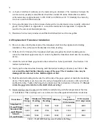
Page 8: ...d and black gage leads to the readout box Select position B See Section 3 for readout instructions 4 Gently pull on the transducer housing until the desired reading is obtained see Table 1 Do not extend the shaft further than the range of the gage The transducer also may be damaged if it is allowed to free fall through its stroke 5 Hold the desired reading and secure the cable side of the gage aga...

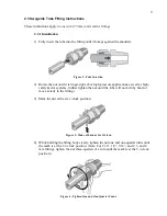
Page 9: ...l as high safety factor systems further tighten the nut until the tube will not turn by hand or move axially in the fitting 3 Mark the nut at the six o clock position Figure 3 Make a Mark at Six O clock 4 While holding the fitting body steady tighten the nut one and one quarter turns until the mark is at the 9 o clock position Note For 1 16 1 8 3 16 and 2 3 and 4 mm fittings tighten the nut three ...

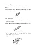
Page 10: ...3 Inspect the ferrules for damage and replace if necessary If the ferrules are replaced the connector should be treated as a new assembly Refer to the section above for installation instructions 4 Reassemble the fitting by inserting the tube with preswaged ferrules into the fitting until the front ferrule seats against the fitting body Figure 6 Ferrules Seated Against Fitting Body 5 While holding ...

Page 11: ...illed with epoxy to waterproof the connections When properly made this type of splice is equal or superior to the cable itself in strength and electrical properties Contact Geokon for splicing materials and additional cable splicing instructions Cables may be terminated by stripping and tinning the individual conductors and then connecting them to the patch cord of a readout box Alternatively a co...

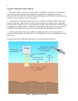
Page 12: ...nt cable exits the structure being monitored The enclosure has a removable top to allow the customer to service the components or replace the board in the event that the unit is damaged by a lightning strike A connection is made between the enclosure and earth ground to facilitate the passing of transients away from the displacement transducer See Figure 8 Plasma surge arrestors can be epoxied int...

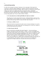
Page 13: ...ors with blue representing the shield bare To turn the GK 404 on press the ON OFF button on the front panel of the unit The initial startup screen will display Geokon Inc GK 404 verX XX After approximately one second the GK 404 will start taking readings and display them based on the settings of the POS and MODE buttons The unit display from left to right is as follows The current Position Set by ...

Page 14: ...he male connector until it locks into place 3 2 2 Sensors with Bare Leads Attach the GK 403 2 flying leads to the bare leads of a Geokon vibrating wire sensor by connecting each of the clips on the leads to the matching colors of the sensor conductors with blue representing the shield bare 3 2 3 Operating the GK 405 Press the button labeled POWER ON BLUETOOTH A blue light will begin blinking signi...

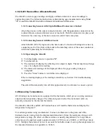
Page 15: ...e one or two digits while reading 4 The thermistor reading will be displayed above the gage reading in degrees centigrade 5 Press the Store button to record the value displayed If the no reading displays or the reading is unstable see Section 5 for troubleshooting suggestions The unit will automatically turn off after approximately two minutes to conserve power 3 4 Measuring Temperatures All vibra...

Page 16: ...ion see Section 2 2 G is the calibration factor usually millimeters or inches per digit F is an optional engineering units conversion factor see Table 2 From To Inches Feet Millimeters Centimeters Meters Inches 1 12 0 03937 0 3937 39 37 Feet 0 0833 1 0 003281 0 03281 3 281 Millimeters 25 4 304 8 1 10 1000 Centimeters 2 54 30 48 0 10 1 100 Meters 0 0254 0 3048 0 001 0 01 1 Table 2 Engineering Units...

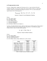
Page 17: ...determined that the thermal coefficient K changes with the position of the transducer shaft Hence the first step in the temperature correction process is to determine the proper thermal coefficient based on the following equation K R1 TM TB G Equation 4 Thermal Coefficient Calculation Where R1 is the current reading TM is the multiplier from Table 3 TB is the constant from Table 3 G is the calibra...

Page 18: ...97 168 Dcorrected 10 165 mm 4 3 Environmental Factors Since the purpose of the displacement transducer installation is to monitor site conditions factors that may affect these conditions should always be observed and recorded Seemingly minor effects may have a real influence on the behavior of the structure being monitored and may give an early indication of potential problems Some of these factor...

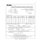
Page 19: ...19 Figure 11 A Typical Calibration Sheet ...

Page 20: ...r shaft is fully retracted with the alignment pin inside the alignment slot as shown in Figure 1 the readings will likely be unstable because the vibrating wire is out of its specified range Is there a source of electrical noise nearby Likely candidates are generators motors arc welding equipment high voltage lines etc If possible move the instrument cable away from power lines and electrical equi...

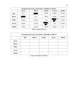
Page 21: ... infinite infinite infinite White infinite infinite N A 3000Ω at 25 C infinite Green infinite infinite 3000Ω at 25 C N A infinite Shield infinite infinite infinite infinite N A Table 4 Sample Resistance Vibrating Wire Sensor Lead Grid SENSOR NAME Red Black White Green Shield Red Black White Green Shield Table 5 Resistance Work Sheet ...

Page 22: ...2 83 107 9 123 77 66K 36 8006 4 1363 44 331 5 84 105 2 124 72 81K 35 7618 5 1310 45 321 2 85 102 5 125 68 30K 34 7252 6 1260 46 311 3 86 99 9 126 64 09K 33 6905 7 1212 47 301 7 87 97 3 127 60 17K 32 6576 8 1167 48 292 4 88 94 9 128 56 51K 31 6265 9 1123 49 283 5 89 92 5 129 53 10K 30 5971 10 1081 50 274 9 90 90 2 130 49 91K 29 5692 11 1040 51 266 6 91 87 9 131 46 94K 28 5427 12 1002 52 258 6 92 85...

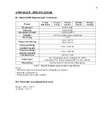
Page 23: ...0 F Frequency Range standard model 1200 2800 Hz Frequency Range slim stick model 1700 3600 Hz Coil Resistance 180 Ω 10 Ω Cable Type Two twisted pair four conductor 22 AWG Foil shield PVC jacket nominal OD 6 3 mm 0 250 Dimensions See Sections A 3 and A 4 for dimensions Table 7 Model 4450 Displacement Transducer Specifications Notes Minimum greater resolution possible depending on readout Depends on...

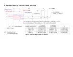
Page 24: ...24 B 3 Dimensions Drawing for Ranges of 50 mm 2 and Below Figure 12 Dimensions Ranges of 50 mm 2 and Below ...

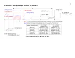
Page 25: ...25 B 4 Dimensions Drawing for Ranges of 100 mm 4 and Above Figure 13 Dimensions Ranges of 100 mm 4 and Above ...

Reviews: