background image

23

Troubleshooting

The following information attempts to address the most probable 
mechanical and user issues with the press. Most issues with heat transfer 
presses are application related. That is, they have to do with the results 
of a particular transfer application. 

For technical support on problems having to do with the final results 
of a particular transfer paper or media, please contact the supplier of 
that transfer media. Generally, the machinery manufacturer is unable 
to support the myriad of different transfer papers, inks and imprintable 
items on the market from other resellers.

Q. 

The timer does not start when I close the heat platen, or the timer 

does not reset when I open the press up.
A. 

There are several probable causes for this. The timer is activated 

by a micro-tilt-sensor stuck to the pressure arm. First: When the head of 
the machine is opened, the tilt sensor needs to be tilted slightly upward 
to signal the controller to stop/reset. When the head of the machine 
is closed, the timer sensor needs to be tilted downward (towards the 
floor) to signal the controller to start counting. Second: Check the wire 
connection from the tilt sensor into the control panel. The timer & 
pressure signals go to a small black 6-pin connector on the top of the 
circuit board in the control box. Check to make sure this is firmly seated 
and plugged into the board. 

Q. 

The control displays Err when it first comes on, and I can not set 

the temperature or use the press.
A. The 

Err message will display if the heating signal from the platen 

has been cut off, interrupted, or the heating sensor has failed. First check 
the Lime Green temperature connector that plugs into the digital control. 
At the top of the controller, there is a green connector that plugs in with 
2 small wires. This is the temperature sensor wire. Check to make sure 
is it properly seated. If after unplugging and plugging the lime green 
connector the Err message still appears. unplug the green connector and 
remove the 2 tiny wires from the lime green plug. Cut them back 1/4” 
and strip them so they have new connections. Reconnect them to the 
lime green plug so they are screwed in tightly and can not pull out. Plug 
the green plug back in and turn the press on.

Summary of Contents for Digital Knight DK16

Page 1: ...1 Version 1 09 Digital Knight DK20 16x20 and DK16 14x16 Digital Clamshell...

Page 2: ...ing Programming a Preset 12 A Walkthrough Tutorial for using Presets 13 User Menus 14 Entering the user menus options 14 Fahrenheit Celsius 14 Timer Counter Units 14 Recorded Pressings User Odometer 1...

Page 3: ...uccessful and easy as possible Please take the time now to thoroughly read through this manual to become acquainted with them It will explain some key features concepts and methods that will save much...

Page 4: ...The height of the bench work space the press is located on would be ideally 27 to 32 high The higher the press the more difficult to close lock Attach the power cord from the rear to the backside of t...

Page 5: ...set point temperature The right side of the screen will also indicate the timing status by stating OPEN TIMING or DONE The DONE indicator may remain on in some cases until the press is opened back up...

Page 6: ...sed for 5 seconds before a main pressing cycle of 20 seconds the Prepress timer can be set for 5 secs and the main timer for 20 When the operator closes the press the 5 sec time counts down When the o...

Page 7: ...k click clamp sound will result when locking the press in place To decrease the pressure turn the pressure knob to the right clockwise The top head will rise away from the lower table To increase the...

Page 8: ...nge A good medium pressure for most applications would be 4 to 6 Excessively high pressure for demanding items would be 7 to 9 Digital Pressure Bar Graph The DK20 and DK16 are upgradable to an automat...

Page 9: ...and reduce the life of the silicone pad When pressing rigid substrates plastics metals woods etc be sure that any protective films or laminates are removed before heating Always check that the transfe...

Page 10: ...e that warns the operator of a possible thermal run away of the press This means the press relay may be locked in a heating position where it will never stop heating to a possibly harmful temperature...

Page 11: ...urrent settings This is simply a reference a reminder of what pressure setting the operator must adjust for that preset Thereare2mainfunctionstousingthepresets LOADINGandEDITING the preset LOADING a p...

Page 12: ...reset Press the TEMP key The Prepress time will flash Use the Arrow Keys to set the Prepress time Set the Prepress time to 00 if only one timer is to be used for that preset Setting Prepress to 00 wil...

Page 13: ...re ref to 8 with the arrow keys Press TEMP Press PRG to leave the preset mode Presets SET 01 and SET 02 have now been programmed Part 2 Loading the presets Let s say we are powering on the machine and...

Page 14: ...ature setting or preset modes may be activated instead Turn the press off and then on and try again Fahrenheit Celsius The current and set temperature can be displayed in F or C After entering the use...

Page 15: ...e the arrow keys to reset the counter to 0 Press PRG to move to the next menu item Pressure Minimum To reset and redefine 0 for the pressure bar graph use this calibration menu Do NOT adjust this sett...

Page 16: ...Press PRG to move to the next menu item Temperature Drop Sense The press can be set to alarm if the temperature drops a certain range below the set temperature This is useful to warn the operator if...

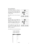
Page 17: ...rent beeping patterns This can differentiate between multiple presses and allow the operator to have a short beep or a continuously repeating beep After entering the user menus see top of page 14 Pres...

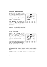
Page 18: ...e arrow keys to set it to ON or OFF Press PRG to move to the next menu item Prepress Timer The press can cycle back and forth between two distinct timer settings the normal countdown timer and a 2nd P...

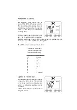
Page 19: ...e set to ON for this menu to be visible Use the arrow keys to set AL2 to OFF or 1 through 10 Press PRG to move to the next menu item denotes a short beep _ denotes a longer beep denotes infinite loop...

Page 20: ...operation The pressure adjustment screw is an area of wear and stress on the machine and should be checked occaisionally for loss of threading Check the threads of the pressure screw and the pressure...

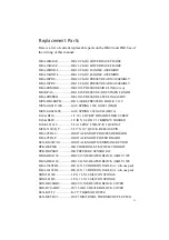
Page 21: ...6 FAS AB38 3 8 X SOCKET HD SHOULDER SCREW FAS GB38U 3 8 ID X 3 4 OD 1 32 BRONZE WASHER FAS EL51618 5 16 18 ZINC TWO WAY LOCK NUT MEN 5162 QP 5 16 X 2 QUICK RELEASE PIN DKA CTRLC DIGITAL KNIGHT PROCESS...

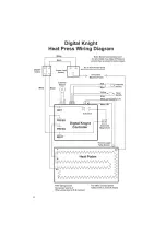
Page 22: ...22 Wiring Diagram...

Page 23: ...r needs to be tilted downward towards the floor to signal the controller to start counting Second Check the wire connection from the tilt sensor into the control panel The timer pressure signals go to...

Page 24: ...eir original force These hydraulic lifter springs are extremely easy to replace and are a surprisingly similar or even lower cost than conventional mechanical springs Contact the factory for replaceme...

Page 25: ...ective press to the factory for repairs if on site component replacement is deemed not possible by Geo Knight Co A return authorization must be granted by Geo Knight Co prior to its return If a press...

Reviews: