background image

Service Manual FL 40-CrossPointer SP 

1

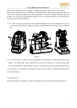
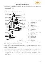
Turn on the screw of the bracket part (6), take off the bracket part (6) from the main unit. 

2

Use  a  cross  screwdriver  to  turn  off  4pcs  cross-head  plate  tapping  screw  ST2.2x9.5

5

,  take  off  the 

housing module (1), unfix the connecting pin between the  the 1# circuit board on the  housing and  the core 

part(3), disassemble the housing part(1) 

3

Use a cross screwdriver to turn off 3 pcs cross-head plate tapping screw ST2.9x9.5

3

, and take off the 

core part(3) and the base part(4) 


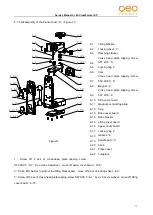
4.1.2 Housing module

1

)(

Figure 8


1

Move off the keypad with a cutter

1-1


2

Use a cross screwdriver to turn off 4 pcs cross-head plate tapping screw ST2.2x5

1-4

, and take off 1# 

operation PC board 

G609-1#operation PC board

(1-3). 

3

Pull a little harder to move off the horizontal window frame part

disassemble the horizontalwindow glass 

(1-6

  and the horizontal window frame

1-5


4

Wipe off the glue on the vertical window glass by a cutter, disassemble the vertical window glass

1-7


5

Use a tweezer to move off 2 closing plugs

1-8

disassemble 

the housing

1-2


                                                Figure 8 


1-1 

Keypad 

1-2 

Housing 

1-3 

1#operation  PC  board/G609-1# 

operation PC board 

1-4 

Cross 

head 

plate 

tapping 

screws ST2.2X5(4) 

1-5 

Horizontal window frame 

1-6 

Horizontal window glass 

1-7 

Vertical window glass 

1-8 

Closing plug

2


1-1

1-2

1-7

1-8(2)

1-6

1-5

1-3

1-4(4)

Summary of Contents for Selection PRO FLG 40-PowerCross GREEN SP

Page 1: ...FL 40 PowerCross SP Service Manual...

Page 2: ...instrument 2 Accuracy calibration 2 1 Setting the reference 2 2 Sort of the error and calibration methods 3 Adjustment for alarming range 4 Disassembly and assembly of the instrument 4 1 Disassembly...

Page 3: ...The hairspring is broken 3 The 1 controling PCB is broken 1 Jointing the broken connecting line 2 Change the broken hairspring 3 Change 1 circuit board Laser line is dim The laser diode is broken Cha...

Page 4: ...adjacent light ruler to the right front of the adjusting platform the 0 position Of the adjacent light ruler should be consistent with the horizontal reference 0 position 2 2 Sort of the error and cal...

Page 5: ...10mm adjust the adjusting screw in two self check hole on point A on the housing of the instrument figure 3 make the horizontal laser line is coincident with the reference line Figure 3 2 2 1 1 2 If...

Page 6: ...figure 3 When adjust the two screws on point D it need to loosen one screw before tighten another screw until the horizontal laser line is coincident with the reference line The degrees of tightness o...

Page 7: ...one screw before tighten another screw until the horizontal laser line icoincident with the reference line The degrees of tightness of the two screws should be nearly the same finally 2 2 3 2 Calibrat...

Page 8: ...3 13 Then move 3 connecting PC board in horizontal make the alarming pole of 2 alarming PC board 3 13 locate in the centre of the alarming ring then fasten the screws When the incline degree of any di...

Page 9: ...th a cutter 1 1 2 Use a cross screwdriver to turn off 4 pcs cross head plate tapping screw ST2 2x5 1 4 and take off 1 operation PC board G609 1 operation PC board 1 3 3 Pull a little harder to move of...

Page 10: ...1 by a cross srewdriver move off 4 alarming PCB G609 4 alarming PCB 3 4 6 Screw off 1 pc of cross head plate screw M2X10 3 9 by a cross srewdriver move off horizontal laser module green laser module...

Page 11: ...ery cover part 4 9 3 Use electric iron to burn down the leading line of the power supply plug move off the contacting part 4 6 4 Screw off 3 pcs of nut M2 5 4 2 by a cross srewdriver move off 6 pcs of...

Page 12: ...board 6 15 6 1 Lifting bracket 6 2 Locking sheet 2 6 3 Damping bracket 6 4 Cross head plate tapping screw ST2 2X5 5 6 5 Locking ring 5 6 6 Cam 6 7 Cross head plate tapping screw ST2 9X9 5 9 6 8 Magne...

Page 13: ...the Locking ring 6 6 17 saperate turnplate 6 22 2 pcs of gasket 6 18 2 pcs of saddle pad 6 19 lifting bracket 6 1 7 Screw off 4 pcs of cross head plate tapping screw ST2 9X9 5 6 7 move off the base co...

Page 14: ...showed in figure 11 connect the corresponding connecting line to each PCBs accordingly Solder 4 hairsprings to the corresponding place of4 Alarming PC board or G609 4 Alarming PC board 3 4 and 3 Conne...

Page 15: ...that note especially Requirement of assembly a Gelatinize 706 glue water on the jointing as follows The interface between base 4 5 and inserting block 4 13 Lifting bracket 6 1 and press cover 6 21 Fin...

Reviews: