Service Manual FL 40-CrossPointer SP
7
3. Maintenance of alarming range
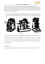
Set up the instrument on adjustable inclined block, alarming range of all sides of the instrument are not
coincident, and the relative differences between fore-and-aft and
right-and-left is bigger, it will influence your usage, then it need to
adjust again. Disassemble the housing parts when repairing, put
the instrument on the horizontal platform, loosen the two screws
(
3-1
)
of alarming ring 2# connecting PC board
(
3-13
)
. Then
move 3# connecting PC board in horizontal, make the alarming
pole of 2# alarming PC board
(
3-13
)
locate in the centre of the
alarming
ring,
then
fasten
the
screws.
When
the
incline degree of any direction is more than 4°, it should appear
alarming if beyond the range. After finishing the adjustment,
fasten two screws of fixing circuit board, and fasten it with 706
glue water (figure 6). Figure 6
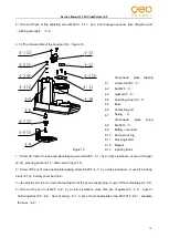
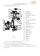
4. Disassembly and assembly of the instrument
4.1 Disassembly of the instrument
4.1.1 Disassembly of the main unit
(
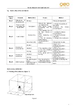
Figure 7
)
Figure 7
1
Housing module
2
Cross-head plate tapping screw
ST2.9X9.5
(
3
)
3
Core part
4
Base part
5
Cross-head plate screw ST2.2X9.5
(
4
)
6
Bracket part
1
2(3)
3
4
6
5(4)


