Service Manual FL 40-CrossPointer SP
9
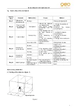
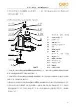
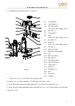
4.1.3 Disassembly of the Core part
(
3
)(
Figure 9
)
Figure 9
1
)
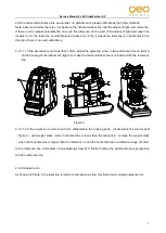
Cut off 4 hairsprings by a electric iron, then cut off the alarming leading line on3# connecting PCB
(
3-2
)
,
then move off the 4 leading line of laser module from the 4# alarming PCB
(
G609-4#Alarming PCB
)(
3-4
)
2
)
Screw off 2 pcs of cross-head plate screws M2X5
(
3-1
)
by a cross srewdriver, take off 3# connecting PCB
(
3-2
)
3
)
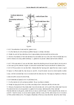
Screw off 2 pcs of cross-head plate screws M2X5
(
3-1
)
by a cross srewdriver, take off 2# connecting PCB
(
3-13
)
and 2 big gaskets
(
3-14
)
4
)
Screw off 2 pcs of cross-head plate screws M2X8
(
3-5
)
, move off the weight stack
(
3-6
)
5
)
Screw off 2 pcs of cross-head plate screws M2X5
(
3-1
)
by a cross srewdriver, move off 4# alarming PCB
(
G609-4# alarming PCB
)(
3-4
)
6
)
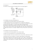
Screw off 1 pc of cross-head plate screw M2X10
(
3-9
)
by a cross srewdriver
,
move off horizontal laser
module
(
green laser module
)(
3-10
)
7
)
Screw off 2 pcs of cross-head plate screw M2X10
(
3-8
)
by a cross srewdriver
,
move off vertical laser
module
(
green laser module
)(
3-12
)
3-1
Cross-head
plate
screws
M2X5(6)
3-2
3# Connecting PC board
3-3
Gemel part/G609-gemel part
3-4
4#Alarming PC board/G609-4#
Alarming PC board
3-5
Cross-head
plate
screws
M2X8(2)
3-6
Weight stack
3-7
Pendulum
3-8
Cross-head sunk screw M2X10
3-9
Cross-head
plate
screws
M2X10(3)
3-10
Horizontal laser module / green
laser module
3-11
Fine adjusting screw M6X10
(
3
)
3-12
Horizontal laser module/ green
laser module
3-13
2# connecting PC board
3-14
Big gasket (2
)
3-1(2)
3-2
3-3
3-1(2)
3-4
3-5(2)
3-6
3-7
3-8
3-9(3)
3-10
3-11(3)
3-12
3-13
3-14(2)
3-1(2)


