


Section 4 • Repair Procedures
4 - 26
GR-20J • GR-26J
Part No. 227656
September 2016
Ground Controls
5-1
Level Sensor
The tilt alarm sounds when the incline of the
chassis exceeds 2° to the side, front or rear.
How to Install and Calibrate the
Level Sensor
Tip-over hazard. Failure to install
or calibrate the level sensor as
instructed will compromise
machine stability and cause the
machine to tip over, resulting in
death or serious injury. Do not
install or calibrate the level sensor
other than specified in this
procedure.
Note: Perform this procedure with the machine on
a firm, level surface that is free of obstructions, and
the machine in stowed position.
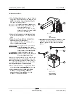
1 Open the turntable cover at the ground control
side of the machine.
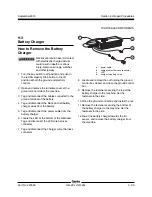
2 Locate the level sensor which is mounted on
the turntable base below the battery charger.
3 Tag and disconnect the level sensor pigtail from
the machine wire harness.
4 After noting the orientation of level sensor
assembly, remove the fasteners securing the
base of level sensor assembly to the chassis.
5 Install the new level sensor onto the machine.
Install and securely tighten the fasteners. Do
not over tighten.
6 Securely install the level sensor pigtail into the
machine wire harness, disconnected in step 3.
7 Remove the plastic cap from the end of the
level sensor calibration wire.
8 Using a length of wire approximately
40 inches / 1 m long, connect the level sensor
calibration wire to the negative post of the
battery.
Result: The green LED underneath the level
sensor flashes several times and stops. The
level sensor calibration is complete.
Result: The green LED underneath the level
sensor does not flash. Check the calibration
wire connection. Contact Genie Industries
Service Department.
Note: The green LED is on during normal machine
operation and it only goes out when the tilt angle of
the machine exceeds 2°.
9 After the green LED stops flashing, disconnect
the calibration wire from the battery, and
securely install the plastic cap removed in
step 7.