background image


Speed Dome Camera Instruction Manual 


10/49


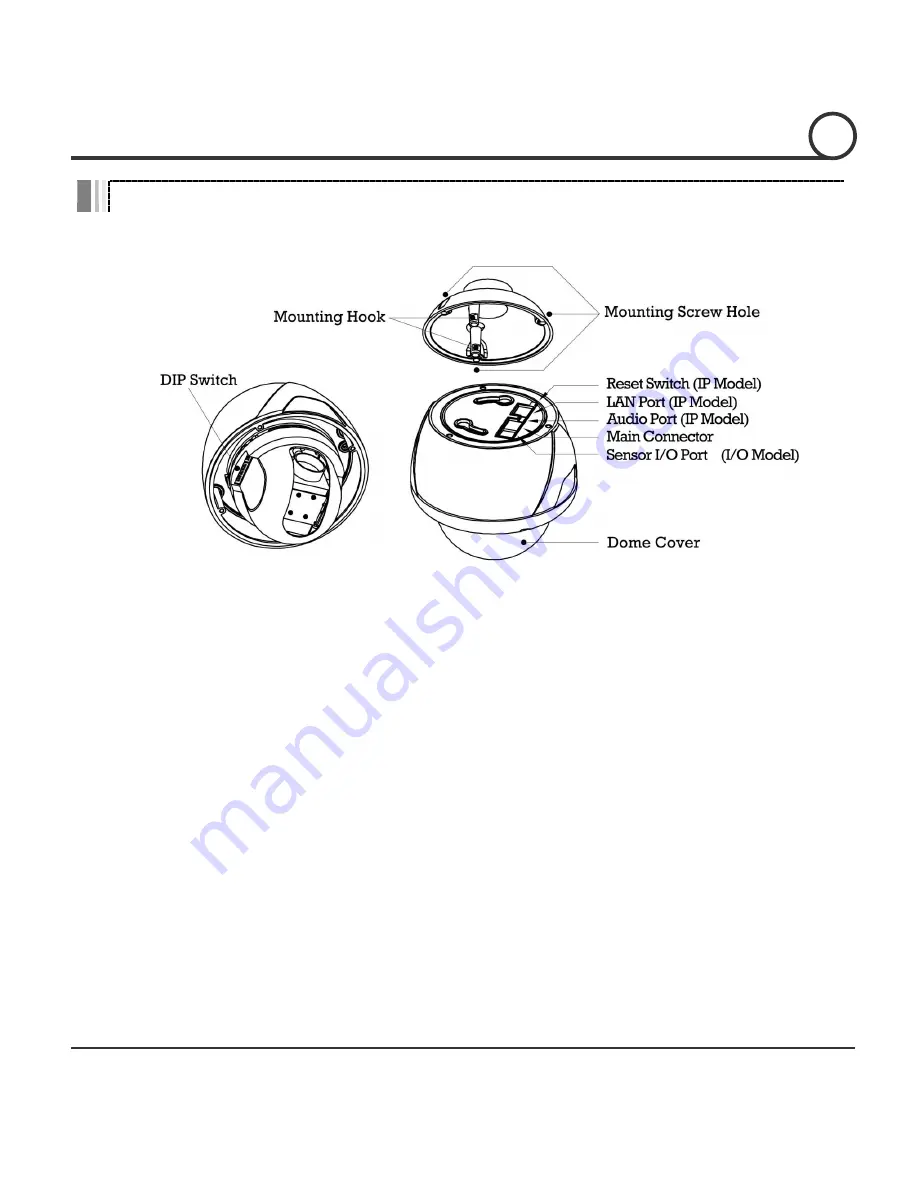
Main Part Description


 Dome Cover 

Do not detach the protection vinyl from the dome cover before 
finishing all the installation process to protect the dome cover from 
scratches or dust. 

 DIP Switch 

Used to set up camera IDs and protocols. 

 Mounting Hook 

Used  to  assemble  the  main  body  with  wall  mount  bracket  or 
ceiling mount bracket. Insert the mounting hooks into the holes on 
the surface of the main body and turn the main body. 

 Mounting Screw Hole  Used to assemble the main body with a bracket with screws. 

 Main Connector 

Used  for  the  power  wire,  the  video  cable  and  the  RS-485 

communication cable connection. 

 Sensor I/O Port 

Used  for  the  sensor  in/out  connection.  (The  sensor  I/O  function 

possible models only) 

 LAN Port 

Used for the Ethernet connection. (IP addressable models only) 

 Audio Port  

Used for the audio in/out connection. (IP addressable models only) 

 Reset Switch 

Used  to  initialize  all  the  network  configurations  to  the  factory 

default.  (IP  addressable  models  only)  Press  the  button  for  more 

than 5 seconds to initialize the network system. 

INTRODUCTION


Summary of Contents for ASD126

Page 1: ...Instruction Guide True Day Night Vandal Resistant 12x Mini PTZ Dome Model ASD126...

Page 2: ......

Page 3: ...in the product s enclosure that may be of sufficient magnitude to constitute a risk of electric shock to persons This exclamation point symbol is intended to alert the user to the presence of importan...

Page 4: ...manufacturer Installation should be done only by qualified personnel and conform to all the instructions by the manufacturer Refer all servicing to qualified service personnel Unless the product is sp...

Page 5: ...he product to shock and vibration as this can damage the product Care must be taken when you clean the clear dome cover Especially scratch and dust will ruin the quality of the product Installation an...

Page 6: ...k Point before Operation 19 Check Points for Preset and Pattern Function before Operation 19 OSD Menu 20 Reserved Preset Hot Keys 20 Preset 21 Swing 21 Pattern 22 Group 23 Other Functions 23 OSD Displ...

Page 7: ...monitor is very natural in monitoring With the Micro Stepping Control Technology the video looks very natural at high zoom magnification during a jog operation on a controller since the camera can be...

Page 8: ...nu is provided to display the status of camera and to configure the functions interactively The information such as Camera ID Pan Tilt Angle Direction Alarm Input and Preset is displayed on screen Ala...

Page 9: ...The fans and heaters are built in in the camera for cold and hot temperature environment Also idealistic mechanical design protects the camera from water and dust IP66 when installed properly with wa...

Page 10: ...ket DefaultAccessories MainCable Wrench AccessoriesforTheModelswithAlarmIn Out Function I OCable AccessoriesforTheIPAddressableModels CrossoverLANCable AudioCable CD Brackets Optional WallMountBracket...

Page 11: ...and turn the main body MountingScrewHole Used to assemble the main body with a bracket with screws MainConnector Used for the power wire the video cable and the RS 485 communication cable connection...

Page 12: ...ff The camera ID range is 1 255 Camera ID must not be 0 The factory default of the camera ID is 1 Match the camera ID with the Cam ID setting of your DVR or Controller to control the camera If you are...

Page 13: ...F PELCO D 9600 bps OFF ON OFF PELCO P 4800 bps ON ON OFF PELCO P 9600 bps Others Reserved Match the camera protocol with the camera protocol in the setting of your DVR or controller to control the cam...

Page 14: ...d signal causes distortion of original signal Accordingly the camera can be out of control In this case the terminal resistor of both sides i e the camera and the controller must be set to ON state Ca...

Page 15: ...system as below Wire the cable s to the ports Insert the mounting hooks into the holes on the surface of the main body and turn the main body Assemble the main both with the camera mount adaptor with...

Page 16: ...em as below Attach the wall mount bracket to the mounting surface Hex Lag 14 50 Pull the wire s and cable s for the system as below Wire the cable s to the ports Insert the mounting hooks into the hol...

Page 17: ...C Connector Video 2 4 Video 5 Red RS 485 3 Yellow RS 485 7 Orange Power 6 8 White Power I O Cable Port Pin Number RJ25 Wire Color Signal 1 Blue IN COM 2 Yellow IN 1 3 Green IN 2 4 Red IN 3 5 Black OUT...

Page 18: ...that the length of the power wire is very long there may be voltage drop and the syatem may not work properly Make the length of the power wire as short as possible RS 485 Communication For PTZ contro...

Page 19: ...ected The sensor types are divided into Normal Open and Normal Close If wrong sensor types are selected alarms should be activated reversely to sensor inputs NormalOpen A sensor activates when a Senso...

Page 20: ...controller manual if the camera can not be controlled properly The operation of this manual is based on the standard Pelco Controller Check Points for Preset and Pattern Function before Operation Chec...

Page 21: ...tput GoPreset 167 SettingZoomProportionalFunctiontoON SetPreset 167 SettingZoomProportionalFunctiontoOFF GoPreset 170 SettingCameraBLC WDRModetoOFF GoPreset 171 SettingCameraBLC WDRModetoON GoPreset 1...

Page 22: ...hat the camera moves repetitively between two preset positions at programmed speeds When a swing function runs the camera moves from the preset assigned as the 1st point to the preset assigned as the...

Page 23: ...Joystick and the preset movement can be memorized in a pattern After a pattern is programmed the remaining storage is displayed in progress bar on the screen To save the recording press NEAR key and t...

Page 24: ...et Pattern Swing and Group to be performed in the event that the power to the camera is cycled This function enables the user to resume after turning on power the last action being executed before tur...

Page 25: ...e Local mode The Global mode is that WB and or AE are is set up totally and simultaneously for all presets The Global parameter setup such as WB and AE can be done in ZOOM CAMERA SETUP menu The Local...

Page 26: ...hen Preset xxx is memorized PRESETxxx When the camera reaches Preset xxx PATTERNx When Pattern x is in action SWG PRESETxxx When Swing x is in action Displays both of Swing number and Preset number UN...

Page 27: ...of the joystick in the controller To save changes press NEAR key To cancel changes press FAR key Main Menu SPEED DOME CAMERA SYSTEM INFORMATION DISPLAY SETUP DOME CAMERA SETUP SYSTEM INITIALIZE EXIT...

Page 28: ...o degree vertical the amount of tilt from zero degree horizontal and current compass direction Also identifies the amount of the zoom magnification ActionTitle ON OFF AUTO Identfies Actions SET PRESET...

Page 29: ...of the system To protect privacy MAX 8 Privacy Masks can be created on the arbitrary position to hide objects such as windows shops or private house With the Spherical Coordinates system powerful Priv...

Page 30: ...Setup EDIT MASK 1 ADJUST MASK WIDTH ADJUST MASK HEIGHT NEAR SAVE FAR CANCEL Move your camera to an area to mask Then a mask and the menu to adjust the mask size will be displayed Adjusts the mask size...

Page 31: ...ual mode at presets Focus data is memorized in each preset in advance and the camera calls focus data in correspondence with presets as soon as camera arrives at presets It should shorten time to get...

Page 32: ...picture output in the red range Blue Adjust 0 255 Adjusts the picture output in the blue range OSD MENU 4 Stabilization ON OFF Compensates image vibrations by wind or others The images with vibrations...

Page 33: ...bled when Iris is Manual mode IRIS AUTO MANUAL 0 64 Adjust Iris value ShutterSpeed A Flicker Manual 1 60 50 1 10000 Sets Shutter Speed This function is disabled when Sens up is Auto mode or WDR is ON...

Page 34: ...UP This setting activates Slow Shutter function when luminance of image signal is too dark It is possible to set up the maximum number of frames piled up one on another by Slow Shutter function This f...

Page 35: ...ation goes up the pan tilt speed goes down Jog Direction INVERSE NORMAL Sets the Jog Direction If this is set to Inverse the view direction in the screen is same as the direction of joystick If this i...

Page 36: ...ssigned function automatically if there is no PTZ command during the programmed Wait Time Wait Time 1 59 sec 1 180 min Wait Time can be programmed from 1 second to 180 minutes Park Action HOME PRESET...

Page 37: ...WING GROUP Selects an action to run when a sensor signal is input Hold Time ENDLESS 1 59 SEC 1 180 MIN Sets the time period for the action which is run by external sensor activation After the time per...

Page 38: ...MAX 10 alphanuberic characteristics are allowed RelayOut Defines the relay output CAMAdjust GLOBAL LOCAL WB White Balance and AE Auto Exposure can be set up independently for each preset There are 2...

Page 39: ...angular is the cursor As soon as finishing selecting an alphabet or a number the cursor moves to the next digit With Left Right Up Down of the joystick move to a desired Alphabet or a desired number i...

Page 40: ...t to the preset assigned as the 2nd point in CW Clockwise direction Then the camera moves from the preset assigned as the 2nd point to the preset assigned as the 1st point in CCW Counterclockwise dire...

Page 41: ...Runs the Pattern for the test purposes to check if it works properly Edit Pattern Edits the selected pattern With the Joystick of your controller move the camera to the start position with an appropri...

Page 42: ...AR EDIT END GroupNumber 1 8 Selects a Group number to edit If the selected Group number is not defined UNDEFINED will be displayed under the selected Group number ClearGroup CANCEL OK Deletes the data...

Page 43: ...the cursor After finishing editing a Action press Near key to go to the previous upper level menu Step Move the cursor Up Down to select an Action number and repeat Step Step to keep editing the sele...

Page 44: ...anual 43 49 EDIT GROUP 1 NO ACTION DWELL OPT 1 PRESET 1 00 03 360 2 NONE 3 NONE 4 NONE 5 NONE SAVE CANCEL After finishing setting up press FAR key to exit Then the cursor will move to SAVE Press Near...

Page 45: ...ris AUTO Shutter Motion Parameters AGC Motion Lock OFF SSNR MIDDLE Power Up Action ON SENS UP AUTO Auto Flip ON Jog Max Speed 120 sec User Defined Data Jog Direction INVERSE Preset 1 128 Undefined Fre...

Page 46: ...al Zoom 12 Digital Zoom ForcalLength F1 6 Wide F2 0 Tele f 3 69 43 32mm AngleofView H 54 44 Wide 4 64 Tele V 41 42 Wide 3 52 Tele MinimumIlluminance 1 2 Lux Colo Sens Off 0 0004 Lux B W Sens 256 50 IR...

Page 47: ...2 Digital Zoom ForcalLength F1 6 Wide F2 0 Tele f 3 69 43 32mm AngleofView H 54 44 Wide 4 64 Tele V 41 42 Wide 3 52 Tele MinimumIlluminance 2 0 Lux Colo Sens Off 0 0008 Lux B W Sens 256 50 IRE F1 6 Da...

Page 48: ...l Pelco D Pelco P Selectable OSD English Menu PTZ information etc Sensor Input 3 Inputs Photo Coupler Type Alarm Outputs 1 Output Relay Output MAX Load DC24V 1A AC125V 0 5A Fan Always ON Heater Operat...

Page 49: ...e ABS External Aluminium DomeSize 107 5mm 4 2 Dimension 158 2 216mm 274 5 227 3mm Weight Approx2 6Kg Approx2 8Kg Note 1 Specification and features are subject to change without prior notice 2 Specific...

Page 50: ...Speed Dome Camera Instruction Manual 49 49 Dimension Indoor Outdoor model Main Body Ceiling Mount Type Wall Mount Type Unit mm SPECIFICATIONS 5...

Page 51: ......

Page 52: ...Edition GN MARCH 2013 GENIE CCTV LTD CCTV House City Park Watchmead Welwyn Garden City Hertfordshire AL7 ILT Tel 44 0 1707 330541 Fax 44 0 1707 330543 www geniecctv com...

Reviews: