background image

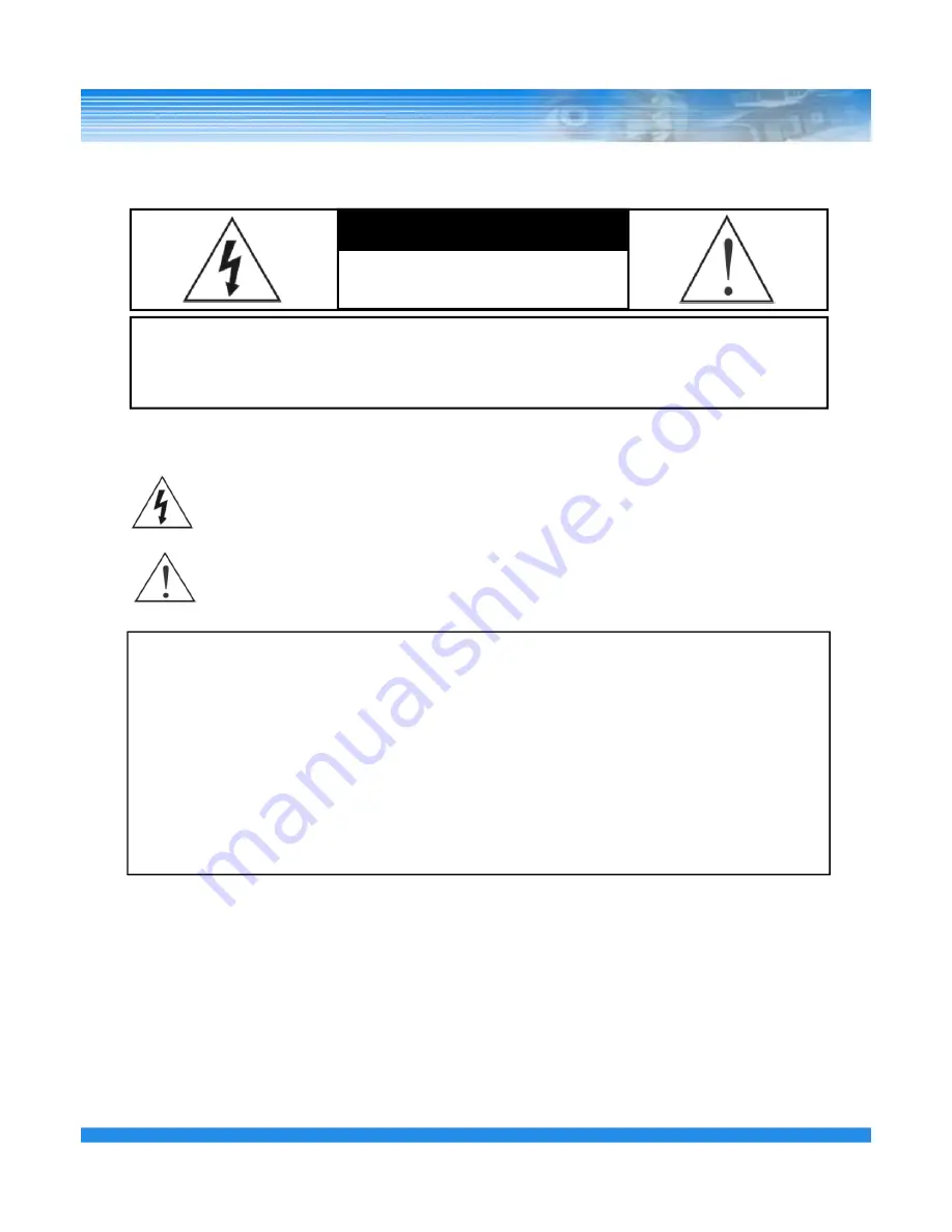
WARNING

RISK OF ELECTRIC SHOCK

DO NOT OPEN

WARNING: TO REDUCE THE RISK OF ELECTRIC SHOCK, 

DO NOT REMOVE COVER (OR BACK).

NO USER-SERVICEABLE PARTS INSIDE.

The lightning flash with arrowhead symbol, within an equilateral triangle, is intended to alert the user to the presence 
of uninsulated “dangerous voltage” within the product’s enclosure that may be of sufficient magnitude to constitute 
a risk of electric shock.

The exclamation point within an equilateral triangle is intended to alert the user to the presence of important 
operating and 
Maintenance (servicing) instructions in the literature accompanying the appliance. 

1

COMPLIANCE NOTICE OF FCC:

THIS EQUIPMENT HAS BEEN TESTED AND FOUND TO COMPLY WITH THE LIMITS FOR A CLASS A DIGITAL 
DEVICE, PURSUANT TO PART 15 OF THE FCC RULES. THESE LIMITS ARE DESIGNED TO PROVIDE 
REASONABLE PROTECTION AGAINST HARMFUL INTERFERENCE WHEN THE EQUIPMENT IS OPERATED 
IN A COMMERCIAL ENVIRONMENT. THIS EQUIPMENT GENERATES, USES, AND CAN RADIATE RADIO 
FREQUENCY ENERGEY AND IF NOT INSTALLED AND USED IN ACCORDANCE WITH THE INSTRUCTION 
MANUAL, MAY CAUSE HARMFUL INTERFERENCE TO RADIO COMMUNICATIONS. OPERATION OF THIS 
EQUIPMENT IN A RESIDENTIAL AREA IS LIKELY TO CAUSE HARMFUL INTERFERENCE, IN WHICH CASE 
USERS WILL BE REQUIRED TO CORRECT THE INTERFERENCE AT THEIR OWN EXPENSE. 

CAUTION:

CHANGES OR MODIFICATIONS NOT EXPRESSLY APPROVED BY THE PARTY RESPONSIBLE 

FOR COMPLIANCE COULD VOID THE USER’S AUTHORITY TO OPERATE THE EQUIPMENT. 
THIS CLASS OF DIGITAL APPARATUS MEETS ALL REQUIREMENTS OF THE CANADIAN INTERFERENCE-
CAUSING EQUIPMENT REGULATIONS.

The information in this manual is believed to be accurate as of the date of publication. The 
information contained herein is subject to change without notice. Revisions or new editions to this 
publication may be issued to incorporate such changes.

Summary of Contents for HDVRQ Series

Page 1: ...HDVRQ HDVRQ HDVRQ HDVRQ Series Series Series Series Digital Video Recorder USER S MANUAL ...

Page 2: ... PROVIDE REASONABLE PROTECTION AGAINST HARMFUL INTERFERENCE WHEN THE EQUIPMENT IS OPERATED IN A COMMERCIAL ENVIRONMENT THIS EQUIPMENT GENERATES USES AND CAN RADIATE RADIO FREQUENCY ENERGEY AND IF NOT INSTALLED AND USED IN ACCORDANCE WITH THE INSTRUCTION MANUAL MAY CAUSE HARMFUL INTERFERENCE TO RADIO COMMUNICATIONS OPERATION OF THIS EQUIPMENT IN A RESIDENTIAL AREA IS LIKELY TO CAUSE HARMFUL INTERFE...

Page 3: ... person and should conform to all local codes 17 Correct Batteries Warning Risk of explosion if battery is replaced by an incorrect type 2 Indicated on the marking label If you are not sure of the type of power please consult your equipment dealer or local power company 8 Power Cords Operator or installer must remove power and TNT connections before handling the equipment 9 Lightning For added pro...

Page 4: ...ion 9 3 DVR ORGANIZATION 10 3 1 Front Panel 10 3 2 Real Panel 11 3 3 Remote Controller 12 4 LIVE 13 4 1 Live Screen 13 INDEX 3 4 1 1 Top Menu 14 4 1 2 Bottom Menu 14 4 1 3 CAMEO Menu 15 5 SETUP 18 5 1 SYSTEM SETUP 18 5 1 1 GENERAL 19 5 1 2 ALARM OUT 21 5 1 3 DISK 21 5 1 4 MONITOR 23 5 1 5 ACCOUT 24 5 1 6 CONFIG 25 5 1 7 SHUTDOWN 26 ...

Page 5: ... 5 3 2 ALARM IN 35 5 3 3 VIDEO LOSS 36 5 3 4 SYSTEM 37 5 3 5 DISPLAY 38 5 4 RECORD SETUP 39 INDEX 4 5 4 1 RESOLUTION 39 5 4 2 SCHEDULE RECORD 41 5 4 3 AUDIO 41 5 4 4 MANUAL 42 5 5 NETWORK SETUP 43 5 5 1 NETWORK 43 5 5 2 SERIAL 45 5 5 3 DDNS 46 5 5 4 E MAIL 47 5 6 SYSTEM INFORMATION 48 5 6 1 SYSTEM LOG 48 5 6 2 STATUS 49 5 6 3 VERSION 51 ...

Page 6: ...Menu 53 6 1 2 Calendar Search 54 6 1 3 Event Search 55 6 1 4 Overlapped List 56 6 1 5 Panorama Search 57 6 1 6 Smart Search 57 6 1 7 Section Repeat Search 58 7 BACKUP 60 7 1 Playback with backup data 61 8 APPENDIX 62 INDEX 5 8 1 Trouble Shooting 62 ...

Page 7: ...fullybeforetheuseof theproduct Readthemcarefullybeforetheuseof theproduct Theresponsibilityfallson theuserto installandusetheproductproperly Theresponsibilityfallson theuserto installandusetheproductproperly Theresponsibilityfallson theuserto installandusetheproductproperly Theresponsibilityfallson theuserto installandusetheproductproperly 6 6 capacity into a single outlet Abnormal heat generation...

Page 8: ...n to prevent from swallowing incidents Keep the battery away from babies If a child swallowed the battery immediately consult a doctor Do not place the container or base filled with water liquids chemicals small piece of metal and heavy object on the product 7 7 power cord Have a technician repair the product If the damaged product is used without repair it may cause electric shock Do not repair o...

Page 9: ...ual Schedule Event Various Search functions Date Hour search Calendar search Event Search Various Playback functions Normal Fast Slow Step Reverse Smart Panorama Repeat Overwrite Recording function 2 OUTLINE 2 1 Functions 8 The DVR menu structure and on screen display is presented in a simple to use and logical GUI format Support 16channel Audio Support Mouse control E mail function Alarm Motion d...

Page 10: ...ystem Organization SMS CAMERA CMS CAMERA KEYBOARD CONTROLLER HDMI VGA MONITOR MIC Video out Network Video input Audio 9 SIREN SENSOR SPEAKER PTZ SPOT MONITOR Audio Input Audio Output Sensors Input Alarm Out ...

Page 11: ...IZATION 3 1 Front Panel Description NOTE Turn on the DVR after connecting the power cord camera input and monitor completely REMOVABLE HDD RACK DVD_RW Menu POWER HDD NETWORK LED 10 Jog Shuttle Number 1 0 Direction ...

Page 12: ... 5 10 8 6 11 7 4 11 Network 7 HDMI Monitor Out VGA out 4 6 Power On off Switch AC Inlet 1 2 HD SDI camera Input 3 HDMI SPOT Out 5 4 e SATA 9 RS 485 2 Alarm out 16 Sensor Input 16 Audio in 1 Out 8 RS 232 11 HD SDI SPOT Out 10 ...

Page 13: ...SE STEP FORWORD FUNCTION POWER ON OFF PLAYBACK PAUSE STOP 12 RECORD DIRECTION MENU ESCAPE How to change remote controller ID A Enter ID button for 3seconds B Power LED is lightened C Enter 2 letters of digit 00 99 In case 00 means no ID function ID set is available from 01 to 99 D Save setting value then LED is off E It enables to communicate the same ID DVR F LED is ON every time data is transfer...

Page 14: ...ed time Motion Icon When motion is occurred Sensor Icon When sensor is occurred Video loss Icon When there is no video input Audio Icon When sound is generated in live mode Freeze Icon When live is paused Sequence Icon When screen is rotated continuously Screen Expand Reduction Window Current Event Information Icon Backup Progress Status Sequence Icon Current Channel Information Icon Current Date ...

Page 15: ... cursor is placed over the end of the top area the top menu is appeared 4 1 1 Top Menu 4 1 2 Bottom Menu 14 In Live screen if button of the remote controller or front panel is pressed or if the mouse cursor is placed over the end of the bottom area the bottom menu is appeared 1 4 7 9 10 13 16 ...

Page 16: ...ERA menu will be appeared 4 1 3 CAMEO Menu 15 CAMEO CHANGE The live camera can be changed to the selected channel If the camera number is selected at the pop up menu shown below the camera is changed to the selected channel FREEZE Live screen of the selected channel can be paused FREEZE ALL Live screen of the all channels can be paused SEQUENCE Live screen is rotated ...

Page 17: ...e Press the ENTER button on PTZ Camera channel Press the ENTER button again then the CAMEO menu will be appeared Select PTZ menu on the Live CAMEO menu Press the ENTER button again the above PTZ menu screen will be appeared Zoom Control In PTZ mode press the Zoom Back button Zoom in Fast reverse play button Zoom out The fast forward play button Focus Control In PTZ mode press the Focus Search butt...

Page 18: ...can be created If the created preset lists are set to ON recording is made with preset tour PATTERN SETUP Pattern can be created by movement zoom focus and iris After pressing the BEGIN button adjust the PTZ camera position or zoom and then press the END button All directions up down left and right zoom and iris settings are recorded PATTERN TOUR PTZ camera moves according to the saved pattern AUT...

Page 19: ...ETUP SETUP SETUP menu icon After select the icon the following LOGIN window will be appeared Enter the password by the key buttons and press the OK button The default password 1 18 5 1 SYSTEM SETUP Select the SYSTEM menu In this category there are General Alarm Disk Monitor Account Configuration and Shutdown ...

Page 20: ...roller BASE CAMERA NO Set the beginning number of camera If set this value to 17 the camera number start with 17 MENU TIMEOUT Keep the Menu screen for this value then escape from Menu RECORD RETENTION Prohibit the playback of passed data Select 0 to 99 days If set 3 days can not playback the data that elapsed 3 days BACKUP CONFIRM Confirm the backup process Log in process HDD OVERWRITE Select on o...

Page 21: ...automatically DATE DISPLAY Display date on live screen or not DATE TIME Change date and time NTP Select the usage of NTP setting DVR time is synchronized with NTP server and get the standard time The default server is pool ntp org and User can input other server Sync now Synchronize immediately Auto Sync Synchronize every day automatically HOLIDAY Add or delete holiday ...

Page 22: ...m device will be operated ALARM CLEAR TEST Press the CLEAR button then alarm device will not be operated 5 1 2 ALARM OUT 21 ALARM CLEAR TEST Press the CLEAR button then alarm device will not be operated INSTALL Display initial HDD install and information NOTE When install HDD first time after install HDD should format by the INSTALL button 5 1 3 DISK ...

Page 23: ... 22 RECORD START TIME Display the earliest recorded data information RECORD END TIME Display the latest recorded data information DISK CHECK Check the data from the earliest recorded to the latest recorded USB RESET Reset the USB connection USB FORMAT Format the connected USB ...

Page 24: ...cted monitor FILTER 5 1 4 MONITOR 23 BORDER COLOR Change the border color ALPHA BLENDING Set the transparency of menu Set 1 to 20 and 20 is closer to the more transparent DISPLAY POSITON ALPHA BLENDING selected screen HDMI selected screen ...

Page 25: ...firm again 5 1 5 ACCOUNT 24 NOTE Default ADMIN password is 1 Initial user name can be modified but can not delete CAUTION Default Admin account must not be deleted before add new user If delete default Admin user before add new Admin user can not access on SETUP menu By the PERM menu can give permission to each ID ...

Page 26: ...default setting DATE Display the latest saved date 5 1 6 CONFIG 25 LOAD Load the saved data SAVE Save the set data DEL Delete the saved data on Slot EXPORT Export the set data to USB or DVD IMPORT Import the set data to USB or DVD IMPORT selected screen EXPORT selected screen ...

Page 27: ... RESTART Restart the DVR SHUTDOWN Shutdown the DVR 5 1 7 SHUTDOWN 26 ...

Page 28: ... Select the camera label of live screen ALL NUMBER NAME OFF NAME Change the camera name If select the camera name the virtual keyboard will be appeared INSTALL Select On Off button to use camera HIDDEN Select On Off button to hide camera on live view Record works correctly NOTE If select INSTALL OFF Camera name and number are not displayed 27 ...

Page 29: ...ard 5 2 2 PTZ 28 PTZ PORT Select the Baud Rate for using PTZ camera ADDRESS Select the ID for using PTZ camera PROTOCOL Show the PTZ protocol list NOTE baud rate data bit parity stop bit ID and protocol depend on PTZ camera for using CAUTION When connect the camera on the RS 485 port refer to the manual of camera manufacturer ...

Page 30: ...splay on spot monitor when sequence is off SEQUENCE Select On Off for sequence screen 5 2 3 SPOT 29 DWELL Select the interval time to move next channel The max value is 256 sec POPUP Select On Off for pop up screen when event is occurred CAMERA selection screen INTERVAL selection screen ...

Page 31: ...sequence means selected camera is rotated in select cameo of division screen 5 2 4 SEQUENCE 30 NOTE CAMEO sequence means selected camera is rotated in select cameo of division screen Camera image which is shown on the other CAMEO of division screen is not included in CAMEO sequence DWELL TIME selected screen CAMERA SELECT screen ...

Page 32: ...a image will be appeared NOTE Move the blue dot to a desired location and press the OK button Drag and move it to include the desired area and press the OK button As a result the area is covered and hidden with the selected color TIP On the screen if click the right button of mouse a menu will be appeared Using this menu a selected area can be delete or saved or returned previous menu ZONE selecte...

Page 33: ...setup 5 3 EVENT SETUP Select the EVENT menu 5 3 1 MOTION 32 INPUT ACTIVE Select On Off to activate motion LEVEL Select the sensitive for motion trigger Select 1 to 5 level AREA Select the motion area TIP If select the ACTIVE LEVEL AREA menu can change all setting at once ...

Page 34: ...uttons NOTE When the status is Red square can move any direction to select When the status is Green color can select motion area or cancel the set area After set the motion area if select the MENU button the following screen will be appeared 33 SELECT ALL Select all motion area CLEAR ALL Clear all motion area SAVE Save the changed setting CLOSE Close the pop up screen EXIT Exit the motion area set...

Page 35: ...elect On Off for buzzer PRESET Set the preset number 34 PRESET Set the preset number When motion is triggered the PTZ camera move to the set preset number position E MAIL Select On Off for e mail notification TIP If select to the DEFAULT only record the channel which is occurred event ...

Page 36: ...RM IN TIP If select the ACTIVE TYPE menu can change all setting at once 35 ACTION RECORD Select the channel for record ALARM Select On Off for alarm BUZZER Select On Off for buzzer PRESET Set the preset number When motion is triggered the PTZ camera move to the set preset number position E MAIL Select On Off for e mail notification ...

Page 37: ... can change all setting at once 36 ACTION RECORD Select On Off for record ALARM Select On Off for alarm BUZZER Select On Off for buzzer PRESET Set the preset number When motion is triggered the PTZ camera move to the set preset number position E MAIL Select On Off for e mail notification ...

Page 38: ... error OFF POPUP POPUP BUZZER THRESHOLD Critical value for Warning CURRENT TEMP Current temperature of the system 5 3 4 SYSTEM 37 DISK DISK FULL WARNING Select ON OFF to disk full warning USED SPACE Display the used space ALARM Select the channel for alarm out BUZZER Select On Off for buzzer MESSAGE Select On Off for message ...

Page 39: ... for e mail notification POWER MENU LOGIN FAIL DISK FULL LOG IN SMART 38 DISPLAY Select display time by second Select 0 to 100 EVENT MESSAGE Select On Off to display event message EVENT POPUP Select On Off to pop up 5 3 5 DISPLAY ...

Page 40: ...lect the record schedule CONTINUOUS SCHEDULE CONTINUOUS DAY TIME Select the day time The night time is changed automatically according to the day time zone WEEKEND Set the weekend zone DAY NIGHT WEEKEND TIME Set the recording frame and resolution by channel EVENT Set the event recording Frame Resolution Post recording time 5 to 100 second ...

Page 41: ... menu TIP For SET1 SET2 SET3 recording change the setting SETUP MODE to CONTINUOUS and enter to the RECORD menu then change the setting 40 RECORD screen after select SCHEDULE menu If set to CONTINUOUS in SCHEDULE menu the DAY NIGHT WEEKEND menu will be changed to SET1 SET2 SET3 Also set the frame and resolution TIP The frame can be set by the direction button in setup screen ...

Page 42: ...ording time Max 60 second POST RECORD Sets Post event recording time Max 100 second 5 4 2 EVENT PRE POST 41 RECORD Select On Off for audio recording by channel 5 4 3 AUDIO TIP If select the RECORD menu can change all setting at once ...

Page 43: ...IC FPS Select the recording frame by each channel Quality Select the resolution by each channel AUDIO Select On Off for audio recording by each channel 42 AUDIO Select On Off for audio recording by each channel ...

Page 44: ...c IP is OFF DVR get IP address from router automatically HOST NAME Type any Host name IP ADDRESS Type IP address Available when DYNAMIC IP is OFF NETMASK Type Subnet mask Available when DYNAMIC IP is OFF GATEWAY Type Gateway Available when DYNAMIC IP is OFF DNS SERVER Type DNS server Available when DYNAMIC IP is OFF CHECK INTERNET Check internet status for use ...

Page 45: ...hen DYNAMIC IP is OFF 44 CLIENT CLIENT ACCESS Select client access options ALL RANGE BEGIN ADDRESS END ADDRESS When select RANGE option type the IP address to accept Input the acceptable IP address SMS WEB PORT TCP Select SMS Web Port REMOTE RESTART Select On Off to restart DVR at remote REMOTE CONFIG Select On Off to change configuration ...

Page 46: ...elect external device MODEL Select the protocol to use 45 PORT Select the Baud Rate DATA bit Parity Stop Bit RS 485 INPUT SETUP SERIAL TYPE Select external device MODEL Select the protocol to use PORT Select the Baud Rate DATA bit Parity Stop Bit ...

Page 47: ...NAME Input the user name from the registered on DDNS server PASSWORD Input the password from the registered on DDNS server ROUTHER IP Select On Off for sending IP information to the DDNS server If use any router this setting should be ON STATUS Check the connection status NOTE For using DDNS server firstly connect the DDNS server and register Host name User name password then input those informati...

Page 48: ...RESS Input the E mail address to receive 47 SERVER MAIL SERVER Select the mail server SMTP server DVR System USER NAME Input the user name USER E MAIL Input the user e mail address SERVER ADDRESS Input the server address SERVER PORT Input the server port LOGIN ID Input the Login ID LOGIN PASSWORD Input the Login password ...

Page 49: ...5 6 SYSTEM INFOMATION In this menu there are System Log Status Version On the Top menu select the INFORMATION menu icon 5 6 1 SYSTEM LOG 48 Check the system log by the left right direction button ...

Page 50: ...5 6 2 STATUS DISK Display HDD Status CHECK SMART NOW Check the smart SMART INFORMATION Show the smart information 49 SMART INFORMATION Show the smart information RECORD Display RECORD Status ...

Page 51: ... AUDIO Display AUDIO Status 50 CAMERA Display CAMERA Status ...

Page 52: ...5 6 3 VERSION Display DVR version and information 51 ...

Page 53: ...e password by the key buttons and press the ENTER button The default password 1 52 QUICK SEARCH Designated time search by User CALENDAR Search by date and time with Calendar EVENT SERARCH Search by event OVERLAPPED LIST Search the overlapped data by changing time GO TO FIRST Search with initial saved data GO TO LAST Search with the latest saved data ...

Page 54: ...earch Screen Recorded Audio Information Icon 53 As in the live screen the top menu can be used in the search screen Play 1 frame backward Fast reverse play Reverse play Pause Play Jump to Start Repeat Exit Search mode Play 1 frame forward Fast forward play Division Screen Jump to the End When mouse cursor is placed over on the bottom side the Search menu is appeared 6 1 1 Search Menu ...

Page 55: ...ayed the orange color 6 1 2 CALENDAR SEARCH 54 b Select the time by the direction button After select hour minutes will be appeared NOTE The time graph color is different by the recording mode Continuous Recording Blue Audio Recording Light Blue Event Recording Red ...

Page 56: ...ent for search VIDEO LOSS Select On Off event for search SELECT CAMERA Select the camera for search 55 HOUR Select time period to see PREV Display previous page NEXT Display next page GOTO Display the image by selected event SELECT CAMERA Select the camera for search VIEW SEARCH LOG Display selected event log ...

Page 57: ...6 1 4 OVERLAPPED LIST If user change the time or applied DST Daylight Saving Time there will be overlapped data 56 After select the list if select the PLAY button can search QUICK SEARCH or EVENT SEARCH ...

Page 58: ...ess the PANORAMA button By mouse click the right mouse button and click the PANORAMA Search Playback with frame by frame 57 6 1 6 SMART SEARCH During normal search press the SMART button Find only event and playback automatically without interval ...

Page 59: ...rch press the LOCK button When press one time the start position is set press one more time the end position is set By mouse click the below red circle button Only playback the set section repeatedly In search screen display the following mark 58 ...

Page 60: ... CAMEO menu FAST REVERSE When reverse play up and down play speed FAST FORWARD When forward play up and down play speed PAUSE Pause the playback FORWARD PLAY Playback the data Remote Controller or Front button Button Explanation in Search mode 59 REVEERSE PLAY Reverse Play the data DISPLAY Display division screen 1 4 9 16 ...

Page 61: ...the ENTER button The default password 1 60 TARGET Select the device to backup USB DVD FROM Select the start date and time TO Select the end date and time BACKUP TITLE Type any title SELECT CAMERA Select the camera for backup EARLIEST RECORD Display the earliest record LATEST RECORD Display the earliest record REQUIRE SPACE Display the data capacity for selected data WRITE Start the backup ...

Page 62: ...er backup the DVR Player is copied with data 7 1 Playback with backup data 61 After backup the DVR Player is copied with data Backup data only can be played on DVR Player at PC Can export to JPEG still shot ...

Page 63: ...uration Default Load O K O K Caution After DVR initialization DVR setting is returned factory default 8 APPENDIX 8 1 Trouble Shooting 62 Caution After DVR initialization DVR setting is returned factory default Need to backup the configuration before initialize DVR Not record on DVR If the recording LED does not flicker check the below items HDD should have enough space otherwise could not be recor...

Page 64: ...ected Audio and turn on CAMEOmenuwillbe appearwhenclicktherightbuttonof mouse CAMEOmenuwillbe appearwhenclicktherightbuttonof mouse CAMEOmenuwillbe appearwhenclicktherightbuttonof mouse CAMEOmenuwillbe appearwhenclicktherightbuttonof mouse Nosoundin search Nosoundin search Nosoundin search Nosoundin search Set to Audio ON If set to OFF sound is not heard during search Although the record icon is l...

Reviews: