General International 90-120 Setup & Operation Manual Download Page 17

17

MAKE SURE THE MACHINE HAS BEEN TURNED OFF AND UNPLUGGED FROM THE POWER SOURCE BEFORE PERFORM-

ING ANY MAINTENANCE OR ADJUSTMENTS.

ADJUSTING BLADE TRACKING

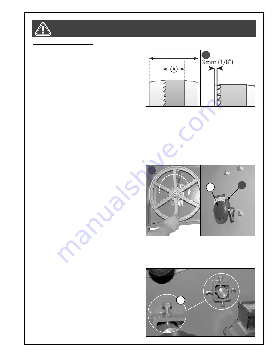
Blade tracking means centering the blade on the 

wheels 

A.

 Ideally, the blade should stay relatively cen-

tered on both the upper and lower wheels. 
Due to natural variations in castings, blade thickness or 

density and tire wear, absolute perfect centering align-

ment is rarely attainable. A slight misalignment of the 

blade on the wheels is inevitable and as long as it is 

kept to a minimum (following the steps listed below) 

will not hinder the performance of the saw.
This misalignment is controlled and kept to a minimum 

by adjusting the tilt angle of the upper wheel. When 

adjusting blade tracking to center the blade on the 

wheels and assuming that perfect centering is not attainable, it is preferable to have the blade slightly off-center 

towards the front of the wheels rather than towards the rear because the teeth on most bandsaw blades have al-

ternating hook (one inner, one outer) – therefore if the blade is centered too far back on the wheel (or if the blade 

tension is too tight), inner hooked teeth will dig into the wheel tire and cause premature wear of the tire. 
Nonetheless, to avoid having the blade come off of the wheels on it’s own during operation, the front edge of the 

blades teeth should never be any closer than 3 mm (1/8”) from the front edge of the wheel 

B

.

To adjust the blade tracking:

B

Note: The upper and lower wheels are factory set to allow 

for easy and optimal blade tracking adjustments using the 

primary blade tracking adjustment knob, which adjusts the 

angle of tilt of the upper wheel. 
In extremely rare cases, if acceptable blade tracking can-

not be attained through the primary adjustment it may 

eventually become necessary to make minor adjustments 

to the angle of tilt of the lower wheel. 
The four bolts F may be adjusted in or out to tilt the lower 

wheel up/down or left/right as needed. Once the adjust-

ment is finished, retighten the the jam nuts.

F

1.

  Open the upper door then rotate the wheel slowly 

forward by hand 

C

 and check the position of the 

blade on the wheel. The blade should remain as 

centered as possible on the wheel as it turns 

A

.

2

.   If the blade tracking must be adjusted, loosen the 

wing nut 

D

 on the tracking adjustment knob 

E

, then 

turn the knob:


Clockwise if the blade moves toward the front of 

the wheel. This tilts the top of the wheel to the back 

and moves the blade toward the center. 


Counterclockwise if the blade moves toward the 

back edge. This tilts the top of the wheel to the front 

and moves the blade toward the center.

Note: Turn the tracking knobs in 1/2 turn increments, re-

check and adjust again as needed.

3.

   With the tracking set, retighten the wing nut 

D

.

C

E

D

Summary of Contents for 90-120

Page 1: ...nsion knob for fast blade changes and adjustments Extra large 21 1 2 x 15 3 4 cast iron table Smooth running heavy duty 1 HP motor Safety lock out switch with removable key to prevent unauthorized use...

Page 2: ...om knowledgeable and qualified sources that it is safe to do so Once you ve read through these instructions keep this manual handy for future reference DISCLAIMER The information and specifications in...

Page 3: ...rd 2 year Limited Warranty or under our Limited Lifetime Warranty all defective parts components or machinery must be returned freight or postage prepaid to General International or to a nearby distri...

Page 4: ...ing to a power source 14 On Off power switch 14 Choosing and changing blades 15 16 Adjusting blade tension 16 Ajusting blade tracking 17 Adjusting the upper blade guides 18 Adjusting the lower blade g...

Page 5: ...16 Do not work on long stock without adequate support on the out feed end of the table 17 Do not push or force stock into the blade The band saw will perform better and more safely when work ing at t...

Page 6: ...ailure still occurs contact a qualified technician or our service department EXTENSION CORDS If you find it necessary to use an extension cord with your machine use only 3 wire extension cords that ha...

Page 7: ...LOCK KNOB I BLADE GUARD LOCK KNOB J BLADE GUARD ADJUSTMENT KNOB K BLADE GUARD L UPPER BLADE GUIDE M MITER GAUGE N BLADE O RIP FENCE P TABLE Q LOWER DOOR LOCK KNOB R BELT TENSION KNOB S CABINET DOOR LO...

Page 8: ...REW 4 I HEX HEAD BOLT M8X40 4 J HEX HEAD BOLT M6X40 4 K HEX HEAD BOLT M6X16 12 L CAP SCREW M6X16 4 M SCREW M5X6 2 N NUT 8 O WASHER LARGE 8 P WASHER MEDIUM 24 Q WASHER SMALL 2 R KNOB 4 S PUSH STICK HAN...

Page 9: ...nd storage Remove it by rubbing with a rag dipped in kerosene mineral spir its or paint thinner Dispose of potentially flammable solvent soaked rags according to manufacturer s safe ty recommendations...

Page 10: ...to the panels as shown and secure using cap screws with washers F and a 5 Allen key 5 Secure the rear panel in place using 4 bolts with washers C and a 10 mm wrench 6 Position the shelf as shown and a...

Page 11: ...NOT GRIP THE BANDSAW BY THE LOWER WHEEL COVER DOOR WHEN LIFTING KEEP HANDS AWAY FROM BLADE AT ALL TIMES INSTALLING THE MACHINE ON THE CABINET 2 Align the 4 mounting holes in the machine with their cor...

Page 12: ...with washers using a 13 mm wrench 6 Tighten the 2 others bolts with washers using a 13 mm wrench 5 To facilitate access to the other 2 mounting holes in the left side loosen the table lock lever count...

Page 13: ...STICK HOLDER 1 Thread the push stick holder in the mounting hole on the left side of the machine and tighten the jam nut with a 10 mm wrench to secure it in place 2 Hang the push stick to keep it hand...

Page 14: ...CTING TO A POWER SOURCE Once the assembly steps have been completed plug the power cord into an appropriate outlet Refer back to the section entitled Electrical Require ments and make sure all require...

Page 15: ...uck in the cut if turned too sharply Narrower thinner blades with finer teeth will cut more slowly but can turn much tighter corners for cutting more intricate work To change blades BLADE SELECTION OP...

Page 16: ...erly ten sioned blade will last longer and be much less likely to break prematurely If the blade tension is too loose you will notice that the blade will have a tendency to drift or slip off line when...

Page 17: ...s on it s own during operation the front edge of the blades teeth should never be any closer than 3 mm 1 8 from the front edge of the wheel B To adjust the blade tracking B Note The upper and lower wh...

Page 18: ...UIDES 1 Loosen the set screws C located on each side of the blade guides using a 3 mm Allen key Note To access the lower guide assembly unlock and tilt the table 2 Adjust the guides by turning the knu...

Page 19: ...aterial Faster speed Soft material Faster speed Blades with few teeth per inch Faster speed SELECTING AND CHANGING THE BLADE SPEED This bandsaw is equipped with 2 speed settings High 3280 Feet Per Min...

Page 20: ...lockwise until the required tension is achieved SELECTING AND CHANGING THE BLADE SPEED CONTINUED ADJUSTING THE UPPER BLADE GUARD The upper blade guard should be adjusted based on the height of the wor...

Page 21: ...ust the blade guard assembly to 1 8 above the workpiece Use both hands while feeding the work into the blade Hold the workpiece firmly against the ta ble Use gentle pressure Do not force the work Al l...

Page 22: ...t use a sharp knife or any kind of solvent When the tires become worn they should be replaced When replacing the tires stretch them around the wheels but do not glue then on MAINTENANCE CLEANING Keep...

Page 23: ...t on the motor pulley Slide the wheel onto the arbor while sliding the belt onto the edge of the wheel pulley A B Push the wheel all the way onto its arbor while turning it until the belt snaps into p...

Page 24: ...ONS QTY 90120C 01 LEFT PANEL 1 90120C 02 THREADED INSERT M6 X 13 5 12 90120C 03 CROSS BRACE 2 90120C 04 WASHER 21 90120C 05 BOLT M6 X 16 16 90120C 06 REAR PANEL 1 90120C 07 RIGHT PANEL 1 90120C 08 KNO...

Page 25: ...DIAGRAM BANDSAW 25...

Page 26: ...CK 1 90120 25 BLADE GUARD 1 90120 26 BLADE GUARD SUPPORT 1 90120 27 PIN 2 90120 28 GEAR 1 90120 29 GEAR SHAFT 1 90120 30 BLADE GUIDE SUPPORT 1 90120 31 SCREW ST4 8 X 22 2 90120 32 KNURLED NUT 2 90120...

Page 27: ...90120 71 WASHER 8 90120 72 LOCK KNOB 2 90120 73 LOCK KNOB 1 90120 74 FLAT WASHER 2 90120 75 ADJUSTMENT KNOB 1 90120 76 HEX HEAD BOLT M8 X 80 1 90120 77 LOWER WHEEL SHAFT 1 90120 78 DUST PORT 1 90120 7...

Page 28: ...0120 109 SHAFT 1 90120 110 POINTER 1 90120 111 CAP SCREW M6 X 35 2 90120 112 RIGHT END CAP 1 90120 113 RAIL 1 90120 114 WING BOLT 4 90120 115 LEFT END CAP 1 90120 116 HANDLE 1 90120 117 HANDWHEEL 1 90...

Page 29: ...NOTES...

Page 30: ...Follow us 8360 Champ d Eau Montreal Quebec Canada H1P 1Y3 Tel 514 326 1161 Fax 514 326 5565 Parts Service 514 326 5555 Order Desk orderdesk general ca www general ca...

Reviews: