


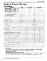


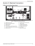


Electrical Connections
16
Installation Manual for Generac PWRCell Inverter
Grounding Bar Wiring
•
Bond the inverter enclosure to the equipment
grounding conductor of the normal power source
power feeder.
•
The grounding bar provides central grounding for
up to 8 conductors.
•
Input and output circuits are isolated from the
enclosure.
•
The neutral conductor is not bonded to the
equipment ground terminal bar within the
enclosure.
•
The inverter and its connected PV and battery
sources are not separately derived systems.
•
DC system grounding is critical for REbus
communications. REbus grounding wires are used
as communications wires. Ensure the following
REbus devices have a low resistance wired
connection back to the inverter grounding terminal
bar:
– PV Link
– PWRcell batteries
•
Torque all terminals as specified in
.
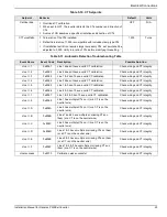
Table 5-4. Terminal Torques
Wiring Terminal
Torque
AC terminals
13.3 to 15.9 in-lb (1.5 to 1.8 Nm)
DC terminals
12 in-lb (1.35 Nm)
Ground terminals
4 to 6 AWG: 45 in-lb (5 Nm)
8 AWG: 40 in-lb (4.5 Nm)
10 to 14 AWG: 35 in-lb (4 Nm)
STOP terminals
1.9 to 2.2 in-lb (0.22 to 0.25 Nm)
Table 5-5.
Grounding Bar Wiring Terminal
Spe
cifications
Wire Size (AWG)
Torque
4-6
45 in-lb (5 Nm)
8
40 in-lb (4.5 Nm)
10
30 in-lb (4 Nm)
(000607a)
Equipment damage. Never connect REbus conductors
to ground. Connecting REbus conductors to ground
could result in equipment or property damage.
CAUTION


