


Electrical Connections
Installation Manual for Generac PWRCell Inverter
15
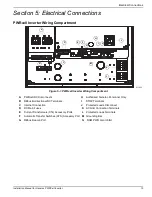
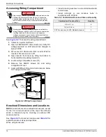
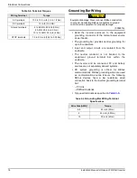
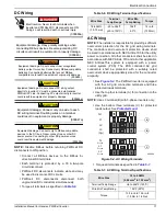
Figure 5-3. Knockout Locations
Wiring Guidelines
•
The inverter shall be installed in accordance with
NEC Article 705.
•
Proper installation techniques must be employed to
restrain service loops and to separate AC, DC and
isolated circuits.
•
All conductors must be rated for at least 420 V.
•
Always use wiring methods in accordance with
National Electrical Code (ANSI/NFPA 70) or other
applicable codes.
•
Field terminals are for copper conductors only.
•
Do not use field wiring leads smaller than 18 AWG.
•
All field installed conductors within the unit are
sized in compliance with NEC Article 310.
•
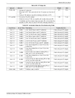
Torque all terminals as specified in
.
42 mm
1-21/32 in
50 mm
1-31/32 in
137 mm
5-13/32 in
97 mm
3-13/16 in
140 mm
5-17/32 in
2-13/16 in
72 mm
56 mm
2-7/32 in
40 mm
1-19/32 in
552 mm
21-23/32 in
50 mm
1-31/32 in
45 mm
1-3/4 in
55 mm
2-5/32 in
55 mm
2-5/32 in
26 mm
1 in
58 mm
2-9/32 in
62 mm
2-7/16 in
50 mm
1-31/32 in
48 mm
1-7/8 in
55 mm
2-5/32 in
55 mm
2-5/32 in
35 mm
1-3/8 in
10 mm
13/32 in
28 mm
1-3/32 in
011234
(000642)
DANGER
Electrocution. Verify all system voltages are safe before
wiring. Disconnect all AC and DC sources of power before
touching terminals. Failure to ensure no dangerous
voltages are present on conductors and terminals before
wiring will result in death or serious injury.
(000599)
Electrocution. Turn battery disconnect OFF and
de-energize REbus before touching terminals.
Failure to do so will result in death, serious injury,
equipment and property damage.
DANGER


