background image

2

Owner’s Manual for Power Zone Connectivity Server

Introduction and Safety

NOTE: 

Notes contain additional information important to 

a procedure and will be found within the regular text of 
this manual.

These  safety  alerts  cannot  eliminate  the  hazards  that
they indicate. Common sense and strict compliance with
the  special  instructions  while  performing  the  action  or
service are essential to preventing accidents.
The  operator  is  responsible  for  proper  and  safe  use  of
the  equipment. The  manufacturer  strongly  recommends
that if the operator is also the owner, to read the owner’s
manual and thoroughly understand all instructions before
using  this  equipment.  The  manufacturer  also  strongly
recommends  instructing  other  users  on  how  to  properly
start  and  operate  the  unit.  This  prepares  them  if  they
need to operate the equipment in an emergency.

General Hazards

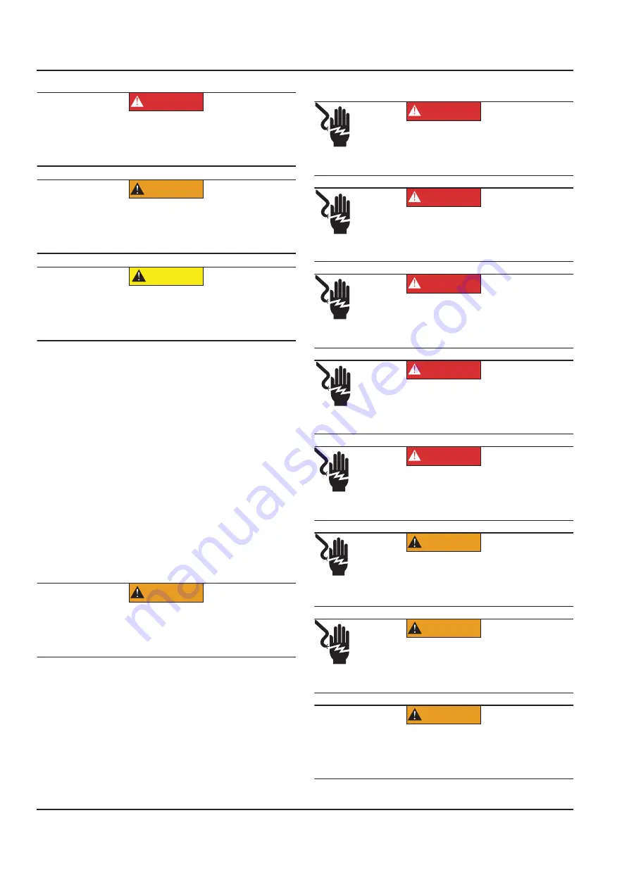
Electrical Hazards

(000001)

DANGER

Indicates a hazardous situation which, if not avoided, 
will result in death or serious injury.

(000002)

WARNING

Indicates a hazardous situation which, if not avoided,
could result in death or serious injury.

(000003)

CAUTION

Indicates a hazardous situation which, if not avoided,
could result in minor or moderate injury.

(000182a)

WARNING

Equipment damage. Only qualified service personnel may 
install, operate, and maintain this equipment. Failure to 
follow proper installation requirements could result in death, 
serious injury, and equipment or property damage.

(000144)

DANGER

Electrocution. Contact with bare wires, 
terminals, and connections while generator 
is running will result in death or serious injury.

(000152)

DANGER

Electrocution. Verify electrical system is
properly grounded before applying power.
Failure to do so will result in death or serious
injury.

(000188)

DANGER

Electrocution. Do not wear jewelry while 
working on this equipment. Doing so will 
result in death or serious injury.

(000104)

DANGER

Electrocution. Water contact with a power 
source, if not avoided, will result in death 
or serious injury.

(000145)

DANGER

Electrocution. In the event of electrical accident,  
immediately shut power OFF. Use non-conductive  
implements to free victim from live conductor. Apply  
first aid and get medical help. Failure to do so will  
result in death or serious injury.

(000187)

WARNING

Electrocution. Potentially lethal voltages are generated
by this equipment. Render the equipment safe before
attempting repairs or maintenance. Failure to do so
could result in death or serious injury.

WARNING

Electrocution. More than one live high voltage
circuit is present. Disconnect all power
sources before servicing. Failure to do so
could result in death or serious injury.(000563)

(000155a)

WARNING

Electric shock. Only a trained and licensed electrician 
should perform wiring and connections to unit. Failure 
to follow proper installation requirements could result in 
death, serious injury, and equipment or property damage.

Summary of Contents for 10000039844

Page 1: ...SAVE THIS MANUAL FOR FUTURE REFERENCE Owner s Manual Power Zone Connectivity Server ...

Page 2: ...ii Owner s Manual for Power Zone Connectivity Server 000393a WARNING CANCER AND REPRODUCTIVE HARM www P65Warnings ca gov ...

Page 3: ...nner 10 Bottom Banner 11 Home Screen Bargraphs 12 Alarm Ribbon 12 Screen Features 12 Scrolling 12 Language 12 Units of Measure 13 Date Time 13 Health Checkmark 13 Editing 14 Screen Icon Details 15 Home Screen 15 System Dashboard Screen 15 Engine Detail Screen 15 Alternator Detail Screen 16 System Detail Menu 16 Setup Menu 19 Calendars 25 Set Date Time 25 Modules 26 Remote Annunciator Setup 26 Digi...

Page 4: ...iv Owner s Manual for Power Zone Connectivity Server This page intentionally left blank ...

Page 5: ...y and if not installed and used in accordance with the instruction manual may cause harmful interference to radio commu nications Operation of this equipment in a residential area is likely to cause harmful interference in which case the user will be required to correct the interference at his own expense NOTE Changes or modifications not expressly approved by the party responsible for compliance ...

Page 6: ...w proper installation requirements could result in death serious injury and equipment or property damage 000144 DANGER Electrocution Contact with bare wires terminals and connections while generator is running will result in death or serious injury 000152 DANGER Electrocution Verify electrical system is properly grounded before applying power Failure to do so will result in death or serious injury...

Page 7: ...Multi Lingual On Screen Editable Parameters Key Function Monitoring Three Phase Voltage Amperage kW kVA and kVAR Selectable Line to Line or Line to Neutral Voltage Measurements Voltage Frequency Engine Speed Engine Coolant Temperature Engine Oil Pressure Engine Oil Temperature Battery Voltage Warning and Alarm Indication Diagnostics Maintenance Events Information Engine Hourmeter Communications Po...

Page 8: ... Supply Cable 2 wires 16 AWG recommended Communication Ethernet Number of Ports 1 Communication Link 4 wires minimum of 8 pin connector 2 wire Receive and 2 wire Transmit Communication Cable Cat5e 2 twisted pairs Maximum Cable Length 328 ft 100 m Baud Rate Auto Detect 10 100 Mbps Communication RS 485 Number of Ports 1 Communication Link 2 wires Communication Cable 2 wires shielded twisted pair i e...

Page 9: ...Locations Bottom View Figure 2 2 LED Locations Front View NOTE See Connection Details for more information regarding the connections and LEDs A Ethernet Connection C USB Connection B Power and RS 485 Connection PWR_RS485 Connector D HDMI Connection A Power LED Red B Communication LED Green B 009515 D C A B 010080 A ...

Page 10: ...wer Zone Connectivity Server General Information Dimensions Figure 2 3 Connectivity Server Enclosure Dimensions A 6 02 in 152 9 mm 0 01 in 0 3 mm B 3 37 in 85 5 mm 0 01 in 0 3 mm C 1 65 in 42 0 mm 0 01 in 0 3 mm A B C 009516 ...

Page 11: ...on Kit to Mount Outside Generator Enclosure The Connectivity Server can be mounted on top of the generator enclosure for extended Wi Fi range 1 Remove the conduit connector 2 Remove the Control Cabinet cable from Power and RS 485 Connection see Figure 2 1 item B of Connectivity Server 3 Remove any other cables including Ethernet cable connected to Connectivity Server 4 Follow instructions as outli...

Page 12: ...s needed disable Wi Fi Wi Fi Connection 1 See Figure 3 2 On the Power Zone Pro Main Controller Built in Display select System Settings 2 Select Enable to enable Wi Fi Bluetooth Wi Fi and BlueTooth cannot be enabled at the same time Figure 3 2 System Settings and Wi Fi Bluetooth Connection 3 See Figure 3 3 To connect a mobile device to the Connectivity Server using Wi Fi the Wi Fi SSID password and...

Page 13: ... address 192 168 25 1 in the top bar of the browser Ethernet Connection 1 See Figure 3 3 To connect via Ethernet the Ethernet IP Address is required This information can be accessed via the Power Zone Pro Main Controller System Details menu and by selecting Network Info C NOTE The IP address and subnet mask on your PC s Ethernet port must be set to a fixed IP address in the same subnet range as th...

Page 14: ...ition An orange LED indicates the key is in the MANUAL position B Communications Health A blinking green LED indicates the Main Controller is responding to Modbus requests A blinking red LED indicates the Main Controller is not responding to requests C Generator Name Displays the name of the generator The user can give the generator an easy to understand name such as East West or Number 1 See Figu...

Page 15: ...submenu allows editing of engine related configuration parameters C Alternator This icon provides access to the bargraphs showing alternator related information The submenu allows editing of alternator related configuration parameters D System This icon provides access to information such as alarm history system notes dealer information and nameplate data E Setup This icon provides access to the s...

Page 16: ... for emissions related Diagnostic Trouble Codes DTCs Normally these DTCs cannot be cleared manually They will clear when the system has met the required conditions for the required length of time or number of run cycles Figure 3 10 Alarm Ribbon Screen Features Scrolling See Figure 3 11 Use a mouse to move the scroll bars Figure 3 11 Scroll Bar at Edge of Screen Language See Figure 3 12 The screen ...

Page 17: ...system date and time can be set from the E Setup icon Navigate to Setup ĺ Calendar ĺ Date Time Changing the date time on the Connectivity Server means a change to the System Time and this will eventually change all other connected equipment displays and modules in the system This will affect timestamps of data and execution of calendar based commands Figure 3 14 Date Time Health Checkmark See Figu...

Page 18: ...larm Condition Red Figure 3 18 Warning Condition Yellow Editing Editing of configuration parameter values is performed by two methods by entering a value Figure 3 19 or selecting a value using the pull down selection box Figure 3 20 Figure 3 19 Numeric Value Editing with ranges Figure 3 20 Pull Down Selection Box 007525 007526 007526 007528 007529 ...

Page 19: ...on the Add button to add notes and click the Submit button The notes will appear below Routine Maintenance has been added as shown in Figure 3 23 The notes can be edited or deleted by choosing the edit or delete small icons on the notes Figure 3 23 Maintenance Notes Engine Detail Screen See Figure 3 24 The Engine Detail Screen displays bargraphs of measured engine parameters In some cases the read...

Page 20: ...creens Alarms and Warnings See Figure 3 28 The Alarms and Warnings screen displays only active and present alarms and warnings A warning A is considered active when the condition for the warning is present A warning is low severity and does not need to be acknowledged An alarm or shutdown alarm B or C is considered active when an alarm condition is or was present but the alarm has not yet been ack...

Page 21: ...be saved to the storage device attached to the USB port Download log to remote computer 1 Select Export 2 Select Download A file will be downloaded through your browser Send log using email NOTE This is only available if an email server has been configured in the Communications Settings 1 Select Export 2 Select Email 3 Enter email addresses separated by commas 4 Select Send Figure 3 30 Alarm Histo...

Page 22: ...ntenance Remaining screen displays bargraphs and numeric values representing how far an item is into its maintenance cycle in units of percent Maintenance intervals are editable from the E Setup ĺ Calendar screen Figure 3 33 Maintenance Remaining Nameplate Data See Figure 3 34 The Nameplate Data screen displays generator information such as Generator model Production Date Country of Origin kW rati...

Page 23: ...f generator output switch or breaker used The options are Contactor Motorized Breaker No Switch Pramac Cont Switch Dual Fuel Setup See Figure 3 38 Dual Fuel settings if applicable can be set and adjusted using this screen The drop down menu A contains four options Disabled Indicates the dual fuel setup is inactive Digital Pressure Indicates the generator is using a Digital Input Pressure Switch Se...

Page 24: ...ressure sensor and are in the units of that sensor value Figure 3 39 Sensors See Figure 3 40 As a precaution the screen will indicate when a needed sensor channel is not setup for the configuration chosen Select the Setup Channel button A to navigate to the appropriate I O configuration screen If all channels are set this section will be empty If the Apply Changes button B is selected and there ar...

Page 25: ...ters Setting Range and Units Description Enable Enabled or disabled Enables or disables the use of AMF Utility Voltage Upper Limit Volts 103 130 of target voltage Highest allowed utility voltage Utility Voltage Lower Limit Volts 50 97 of target voltage Lowest allowed utility voltage Utility Frequency Upper Limit Hz 103 120 of target frequency Highest allowed utility frequency Utility Frequency Low...

Page 26: ...is dynamically displayed on the screen 3 Use the meter C to read the A B voltage manually 4 Enter the meter reading onto the screen resolution of 0 1 volts 5 Click Calibrate D Calculations will be performed and a new calibration stored for that channel 6 Repeat for readings B C and C A The same procedure can be used for all other channels however for the Amp readings a calibrated clamp meter is re...

Page 27: ...e before the alarm is cleared resolution of 0 1 seconds 4 Enter the type of alarm Warning Alarm or Shutdown E 5 Choose when the alarm becomes active Always Immediate or Hold Off delay F Always means the alarm condition is always being evaluated Immediate means the alarm condition is only evaluated while the generator is rotating Hold Off means the alarm condition is only evaluated after a hold off...

Page 28: ... No Mode Always Immediate and Hold Off 4 Set the GT Setpoint C this is the value above which any reading is considered faulty 5 Set the LT Setpont D this is the value below which any reading is considered fault 6 Enter the number of seconds to delay E after the threshold is reached before triggering the fault 7 Select Apply Changes F to save the settings Figure 3 48 Sensor Fault Setup Event Histor...

Page 29: ...rated current of the generator with a one second delay to trigger indication This screen allows the operator to enable disable GFI change the threshold change the hysteresis for the threshold and change the delay time for triggering the indication Refer to PRGM GFI GROUND FAULT INDICATION POWERZONE part no 10000044416 for setup instructions Figure 3 51 Ground Fault Indication GFI Calendars See Fig...

Page 30: ...e 3 55 the oil was last serviced at 100 engine hours and will need to be serviced again when 200 additional engine hours have been logged at 300 engine hours Figure 3 55 Oil Life Maintenance Setup Modules See Figure 3 56 This screen allows you to select which module you wish to setup The Automatic Voltage Regulator AVR and Governor are covered by the Alternator setup section and the Engine setup s...

Page 31: ...Select the digital input channel to modify by clicking on its name in the Digital Input Diagnostics screen 2 Select the physical input source A 3 Select the function code B 4 Check the Invert box C to change the digital polarity if desired Invert means a grounded input pin will show as HIGH 5 Click Apply Changes D Figure 3 58 DI Setup Digital Output Function DOF Setup To configure a digital output...

Page 32: ...on equation using an up to 10 point translation table or combining the calibration equation and a translation table Analog Input AIN Setup 1 See Figure 3 61 Select an unused channel ID by selecting the analog input channel name in the Analog Input Diagnostics screen Figure 3 61 Analog Input AIN Diagnostics Screen 2 See Figure 3 62 Select the input source a pick list will be displayed of physical d...

Page 33: ...nel ID selects the analog output pin where channel IDs 1 2 are analog voltage and 3 9 are PWM pins 2 Select the source type A as analog or control A different pick list will be displayed for each 3 Select the function code B from the pick list 4 Scale the output C Numbers are entered in the units the source is measured in Enter the value at which the output should be 10 V Enter the value at which ...

Page 34: ... through TCP or RTU Wi Fi and Ethernet Port Setup Static IP Address Configuration for Ethernet 1 See Figure 3 65 Navigate to E Setup ĺ Communications ĺ Ethernet Wi Fi Bluetooth 2 In the Connection mode setting select Static A 3 This mode is selected to assign an IP address IPv4 to the Ethernet interface B 4 IPV4 Address Subnet DNS and Gateway C are set to match the requirements of the host network...

Page 35: ...lient Setup Manual Connection to Access Point The Wi Fi IP address will be assigned by the Wi Fi network Static IP addresses are not supported for Wi Fi connections 1 See Figure 3 68 Click the Manually Enter Wi Fi checkbox A 2 Enter SSID Service Set Identifier B 3 Enter network password C as required by network configuration 4 Click Connect D to connect to wireless network 5 Status message will be...

Page 36: ...tup consists of three steps Turning on Bluetooth on both devices Pairing Performing a separate connect action from each connected device Turn Bluetooth OFF or ON 1 To get to the screen shown in Figure 3 71 go to Settings ĺ Communications ĺ Ethernet Wi Fi Bluetooth 2 Check the Bluetooth Enabled checkbox A to enable or disable Bluetooth 3 Select the Apply button B 4 Follow the connecting device inst...

Page 37: ... the Power Zone Application to load 6 The Connectivity Server can now be accessed using the web browser on the connected device Change Connectivity Server Bluetooth Name 1 See Figure 3 74 Select the text box field and enter a new name A 2 Select Apply Changes B Figure 3 74 Change Bluetooth Name 3 Confirmation of name change is displayed 4 See Figure 3 75 New name is now displayed in name text box ...

Page 38: ...N bus such as Power Zone AVR s Governors and Battery Chargers Email Power Zone features that use email must have access to an SMTP email server See Figure 3 78 This screen allows you to set up the email server and recipient list for alarm and warning emails The name or IP address of the server providing SMTP services is entered in the Host field A The name to be used as the sender of the email is ...

Page 39: ...tion settings To configure the RS 485 port set the slave ID of the Connectivity Server select the RS 485 port from the Serial Port list and set the communication settings Baud Rate Stop Bits and Parity Figure 3 79 Configure Modbus Pass through Tools Menu See Figure 3 80 The Tools menu displays submenus for login configuration file transfer synchroscope J1939 CAN bus diagnostics diagnostics trendin...

Page 40: ...ive Select Save to USB Drive Figure 3 82 Read from Controller The Write to Controller option Figure 3 83 takes an existing configuration XML file and applies those settings to the Main Controller 1 Navigate to Tools ĺ Configuration File Transfer ĺ Write to Controller 2 To use a file stored on your network connected device select the Local tab and select Choose Select the file and select Load 3 To ...

Page 41: ...ynchroscope See Figure 3 87 The Synchroscope screen allows the user to view the synchronization process between the generator and utility A dynamic view of the delta phase angle delta voltage and delta frequency between the generator and utility is shown The outside circle rotates with the intent that when the gap is at the top in line with the red line the parameter is in sync the delta is zero T...

Page 42: ... to draw the graph The minimum value to graph is entered into the text box next to the drop down list B The text box on the far right is used to enter the maximum value to graph C The current value being read is displayed in the middle text box The time interval between readings is selected using the Interval drop down list D The fastest data collection rate supported by Remote Trending is 250 ms ...

Page 43: ...a specific condition is observed To configure a trigger value select the data value that will cause the trigger the comparison operation to use and the level that will cause the trigger to occur E 7 Use the Post Trigger Frames dropdown list F to specify the number of data points that should be collected after the trigger occurs 8 Use the Trending data size radio buttons G to select the number of b...

Page 44: ...r later use by pressing the Save button F or saved and started immediately by pressing the Save and Start button G 3 Once the data has been collected it can be retrieved by downloading it through a browser by pressing the Download button H or have it sent as an attachment in an email by pressing the Email Log button E Figure 3 93 Data Logging Screen PLC Manager See Figure 3 94 The PLC Manager main...

Page 45: ...n the System Update process to completion During a system update the Status column F will display the status of each step of the update process If the Connectivity Server is updated it will automatically reboot During reboot the Connectivity Server will lose connection with other devices including the PC The web browser screen showing the application will time out After reboot is complete the PC w...

Page 46: ...ranslated Power Zone Owner s Manuals or documentation like wiring diagrams for storage and use on the Connectivity Server Only PDF files are currently supported To select a file from a mobile device 1 Select Local File tab A 2 Select Choose B 3 Select a file from your mobile device To select a file from a USB drive attached to the Connectivity Server 1 Select USB on Panel tab C 2 Select List Packa...

Page 47: ...e Tools menu A select Login B This screen provides a keyboard to input a password for access to restricted areas of the app NOTE If not logged in the user will be prompted to enter a password if trying to access a restricted area of the app as shown in Figure 3 102 Figure 3 101 Login Menu Figure 3 102 On screen Keyboard 009624 A B C D E F G H 009633 A B 009634 ...

Page 48: ...44 Owner s Manual for Power Zone Connectivity Server Installation and Operation This page intentionally left blank ...

Page 49: ...ed properly on PWR_RS485 connector to the Power Zone Pro Main Controller BS6 connector Green LED in front of enclosure is OFF Verify the RS 485 wires are connected properly on PWR_RS485 connector to the Power Zone Pro Main Controller BS6 Connector Green LED in front of enclosure is not blinking Operating system or application is not working properly Unplug and plug back the PWR_RS485 cable to the ...

Page 50: ...46 Owner s Manual for Power Zone Connectivity Server Troubleshooting This page intentionally left blank ...

Page 51: ......

Page 52: ... rights reserved Specifications are subject to change without notice No reproduction allowed in any form without prior written consent from Generac Power Systems Inc Generac Power Systems Inc S45 W29290 Hwy 59 Waukesha WI 53189 1 888 GENERAC 1 888 436 3722 www generac com ...

Reviews: